29
PM-833TV 4-13-21V1.indd Copyright © 2021 Quality Machine Tools, LLC
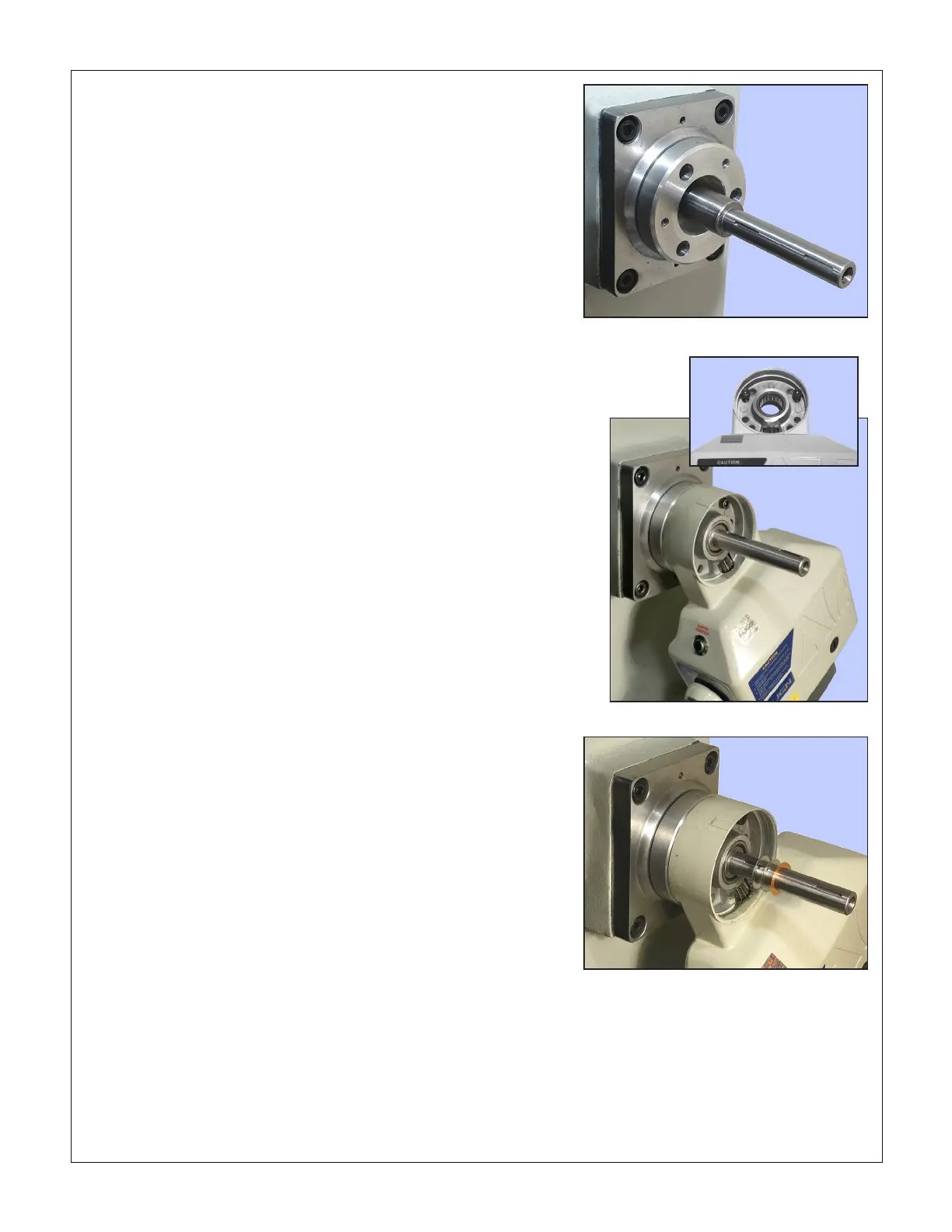
Figure 8 Motor mount collar installed
Figure 9 Motor installed
10. Install a key on the extender shaft. Using the crank handle
removed earlier (not the replacement one), test headstock
motion for smoothness and minimal gear noise. If neces-
sary, optimize by slight adjustment of the main ange, then
fully tighten the four M8 screws.
11. Remove the inner collar from the main ange.
12. Using the same three M6 screws, install the replacement
motor mount collar, Figure 8. It may be a tight t, so tighten
the screws sequentially a turn at a time, then fully tighten.
13. Taking care not to disturb the needle bearing, slide the mo-
tor unit into place, tilted back 30 degrees, Figure 9.
14. Secure the motor with two 1/4-20 x 1" socket head cap
screws in the locations shown inset. Hold the unit up while
doing this to make sure the needle bearing is not pre-load-
ed by the motor's weight.
15. With the 1/4-20 screws fully tightened, check for clearance
between the gray molded lower cover of the motor unit and
the hex head bolt securing the column. If it just touches
without detectably misaligning the motor — no problem. If
you do see an issue here, one option is to insert a shim be-
tween the motor mount collar and the motor. Plastic 0.020"
shim stock is suggested (it's easily cut with scissors). Do
not overdo the shimming, because it reduces the contact
between the extender shaft and needle bearing.
16. Install small shims on the extender shaft, Figure 10. This is
a trial and error process — expect three or four tries to get
it right. Start with a thick shim, if necessary, then progress
to the thin copper shim for ne tuning. The objective is to
hold the brass gear just clear of the motor unit casting
(and/or the needle bearing), with the smoothest possible
mesh. Test by installing the brass bevel gear (no key) ro-
tating it back and forth while holding it rmly in mesh with
the motor gear.
17. Place a key on the inner portion of the extender shaft.
Grease, then install, the brass gear.
18. Install the dial on the brass gear stem. Use large shims to
hold if o the motor casting, Figure 11. This is another trial
and error process.
19. Thread the black knurled ring onto the gear stem to hold
the dial in place. Hand-tighten the ring, then use a crank
handle to check the separation between dial and motor
casting. The shim stack thickness is correct when the dial
is as close in as possible, but not scraping at any point
— especially when the crank is heavily loaded (raising the
headstock).
20. Check that the headstock is at mid-travel, free to move
(clamp levers loosened). Install the knob on the direction
control lever. Set the speed control fully counter-clockwise.
Connect the motor unit to 110V ac power, and switch on.
21. Set the direction lever UP or DOWN, then slowly rotate the
speed control to run the motor. Listen for unusual noises,
which may call for re-shimming in both locations, and/or
nessing the motor attachment (loosen, then re-tighten the
two 1/4-20 screws in the mounting bracket).
22. When satised with the installation, place the keyed wash-
er on the extender shaft, Figure 12 inset.
23. Install the "freewheel" (spring-releasing) crank handle, se-
curing it with the original M8 socket head screw and wash-
er, Figure 1.
Figure 10 Small shim washers on extender shaft
Thee washers were used on the sample machine:
0.024", 0.016" and 0.004".

 Loading...
