28
PM-833TV 4-13-21V1.indd Copyright © 2021 Quality Machine Tools, LLC
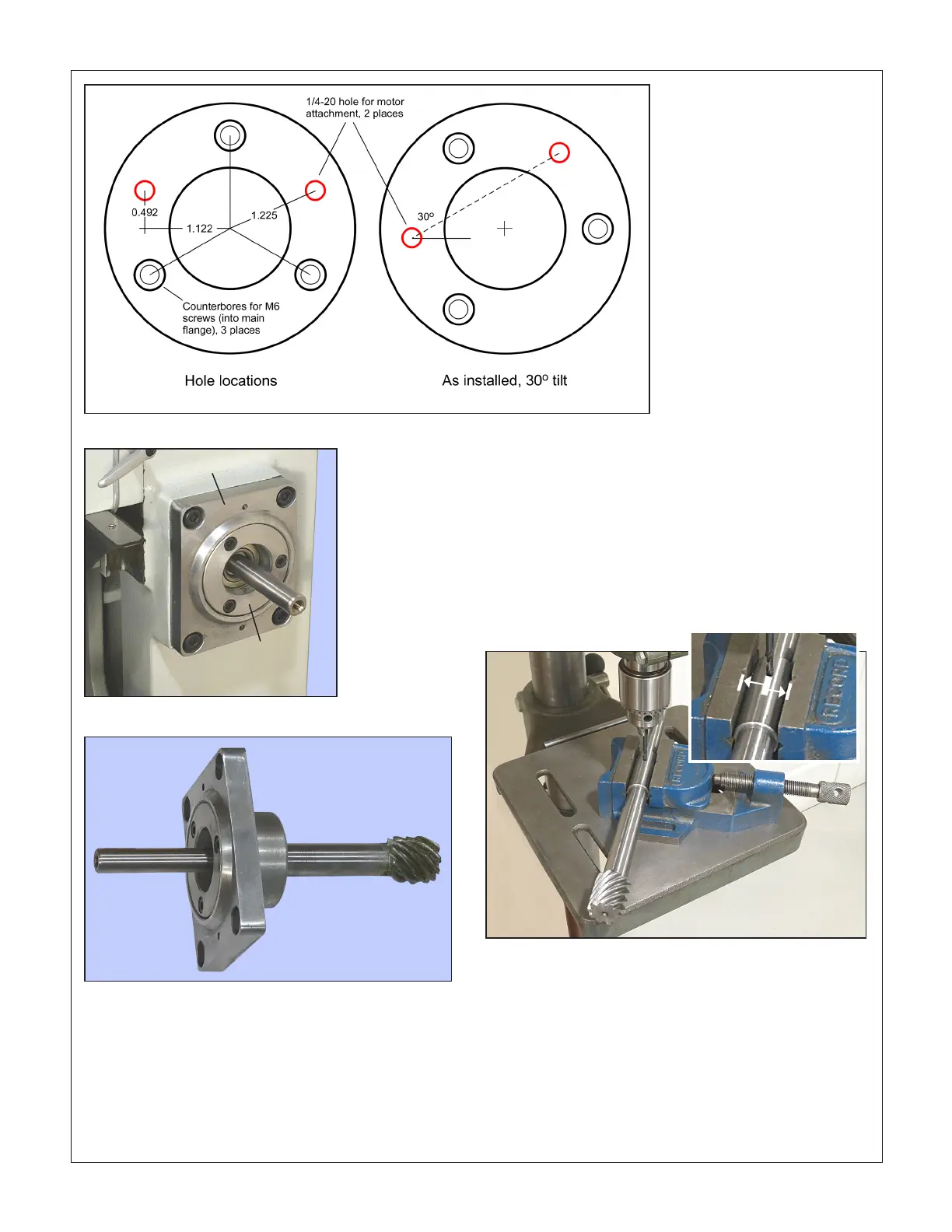
Figure 5 Hand crank components removed
Figure 6 Main ange with original gear shaft
4. Plug the replacement (longer) gear shaft as far as it will go
into the extender.
5. Through-drill #21 or 4 mm the gear shaft to match the holes
in the extender. It is important to drill square in both axes to
avoid diculty when reassembling — all holes should line
up properly when the shaft is rotated 180 degrees in the
extender. A drill vise is recommended, Figure 7, but take
care not to damage the extender surface (one half-inch or
so of the extender runs in the motor unit needle bearing).
It is a good idea to pin the rst hole before drilling the sec-
ond. NOTE The pilot holes in the extender as supplied may
not have been drilled at right angles, radially, so don't drill
the second pair by dead reckoning (in a spin indexer, for
instance). If a vise is available, a quick way to get radial
symmetry is to insert the drill bit, then rotate the extender
for equal distance from opposing jaws, Figure 7, inset.
6. With the extender removed, tap (soft mallet) the replace-
ment gear shaft fully into the main ange, taking care not
to displace the bearings.
Figure 7 Drilling the extender
Inner collar
Main ange
7. The innermost hole in the extender should now be just ac-
cessible for roll pinning. Do this on the bench, or using a
toggle press, avoiding damage to the extender surface.
8. Pin the other hole, then inspect the extender to be sure the
pins do not protrude. If necessary remove any burrs from
the outermost holes (which may come into contact with the
motor's needle bearing).
9. Grease the helical gear. Install the main ange, with ex-
tended gear shaft, on the milling machine column. Snug,
but don't fully tighten, the four M8 screws.
Figure 4 Motor mount collar detail

 Loading...
