16
These amplifiers are designed to work within a 10 to 16.8 volt DC range. Before any
wires are connected, the vehicles electrical system should be checked for correct
voltage supply with the help of a voltmeter.
First, check the voltage at the battery with the ignition in the OFF position. The voltmeter
should read not less than 12V. If your vehicles electrical system is not up to these
specifications, we recommend having it checked by an auto electrician before any
further installation. Once the vehicle is checked, make certain the correct cable size is
used. We recommend using as large a gauge cable as possible, use the Power Cable
Selection Chart
to calculate the correct power wire size for your application.
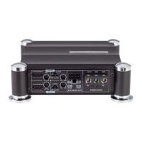
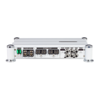
Power
This amplifier should be wired directly to the vehicle battery using the appropriate size
cable. Start at the vehicle battery and run the power cable through to the amplifier.
Avoid running the power cable over engine components and near heater cores. The use
of an online fuse o circuit breaker is a must ; this will prevent the risk of a potential fire
caused by a short in your power cable. Connect the fuse holder or circuit beaker as
close to the battery positive (+) terminal as possible ( no farther then 18" from the
battery).This fuse or circuit breaker should be no greater then the sum of the fuses found
on the chassis of your amplifier (also see specifications chart). You may now connect
the cable to the battery, but remember to leave the fuse out or circuit breaker "off" until
all other cable connections are made.
Ground
When grounding your amplifier, locate a metal area close to the amplifier that is good
source of ground (preferably the floor pan). Once again, investigate the area you wish to
use for electrical wires, vacuum lines, and brake or fuel lines. Use either a wire brush or
sandpaper to eliminate unwanted paint for better contact of the ground. Secure the
ground cable to the body using a bolt, star washer and nut. Spread silicon ove the
wcrew and bare metal to prevent rust and possible water leaks.
Now it’s time to connect the power and ground cable to the amplifier. Cut both cables to
length. Strip off 1/2 -inch (1.2mm) of the insulation so that the bare wire will go all the
way in the terminal block on the side panel of the amplifier, seating it firmly so no bare
wire is exposed. Use a Philips (cross) type screwdriver to loosen the + BATT and the
GND connections on the amplifier. Insert the ground first, and then the + 12V and please
make sure that you place them into the correctly marked terminals.
Then tighten the screws down securely.
Remote
This terminal must be connected to a switched +12V source. Typically, remote turn-on
leads are provided at the source unit that will turn on and off the amplifier in
correspondence with the source.
If the source unit does not have a remote turn-on lead, then a switched +12V supply
must be used, like the ACC, +12v.