5.21i Elliptical Fitness Crosstrainer
Page 25
Procedure 6.3 - Troubleshooting the Speed Sensor
Circuit Description
The speed sensor is a reed switch. A magnet is mounted on the step up pulley. The magnet
passes the speed sensor once per revolution. The output from the speed sensor is a 5 Vdc
square wave, the frequency of which indicates the operating speed. When a square wave output
is not being generated from the speed sensor the system assumes the unit is not in use.
WARNING
Before continuing with this procedure, review the Warning and Caution statements listed in
Section One, Things You Should Know.
Procedure
1. Remove the right rear cover section per Procedure 7.1. Set the on/off switch in the “on”
position. Operate the unit. If the system timer has not started and a stride rate is not
displayed, the speed sensor is not operative. We shall use the presence of a stride rate to
determine when the speed sensor is functioning normally.
2. A magnet must be installed in the step up pulley. If the stride rate is not being displayed in
step 1, verify that a magnet is installed in the step up pulley and that the space between the
end of the reed switch and the step up pulley is approximately 1/8 inch (See Diagram 6.3 for
serial codes F8 and SS or Diagram 6.4 for serial code A998).
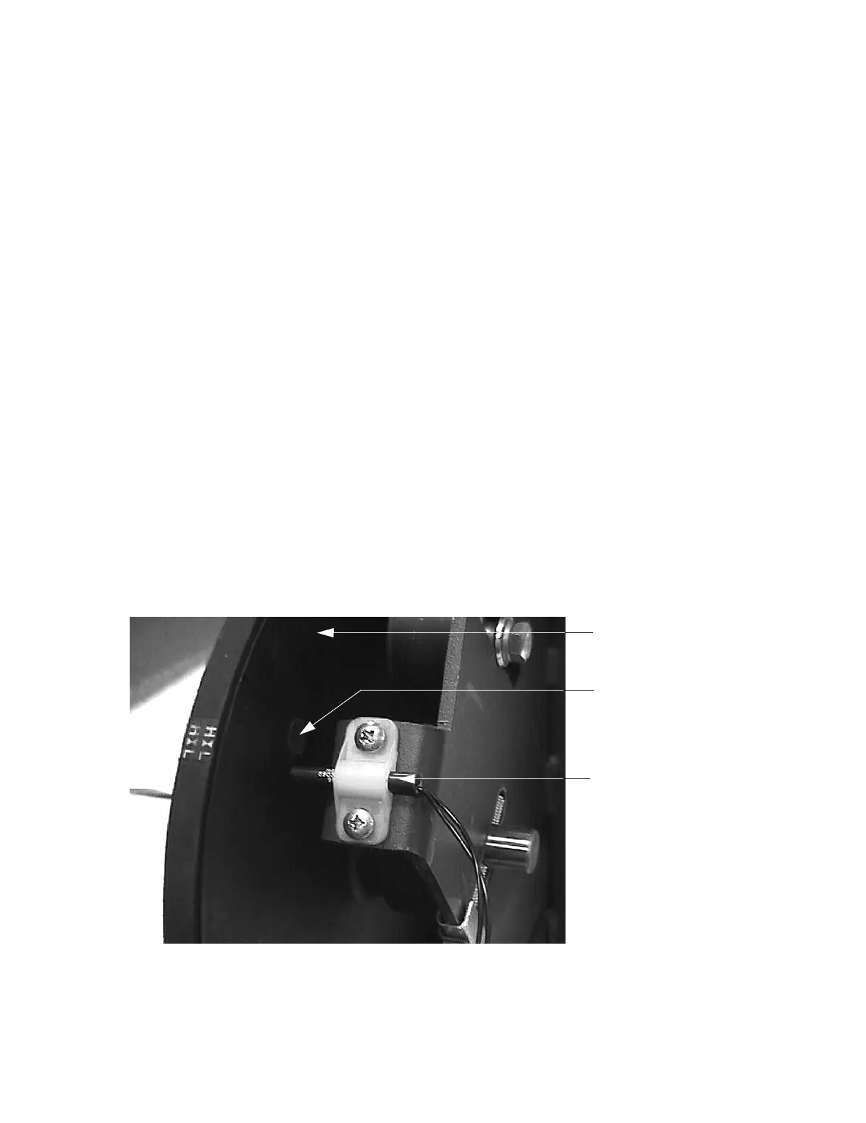
Diagram 6.3 - Speed Sensor (serial codes F8 and SS)
Step
S
Step Up Pulley
Magnet
Reed Switch