EN • 8
ENGLISHFRANCAISNEDERLANDSESpAñoLITALIANoDEuTSCH
664Y3300
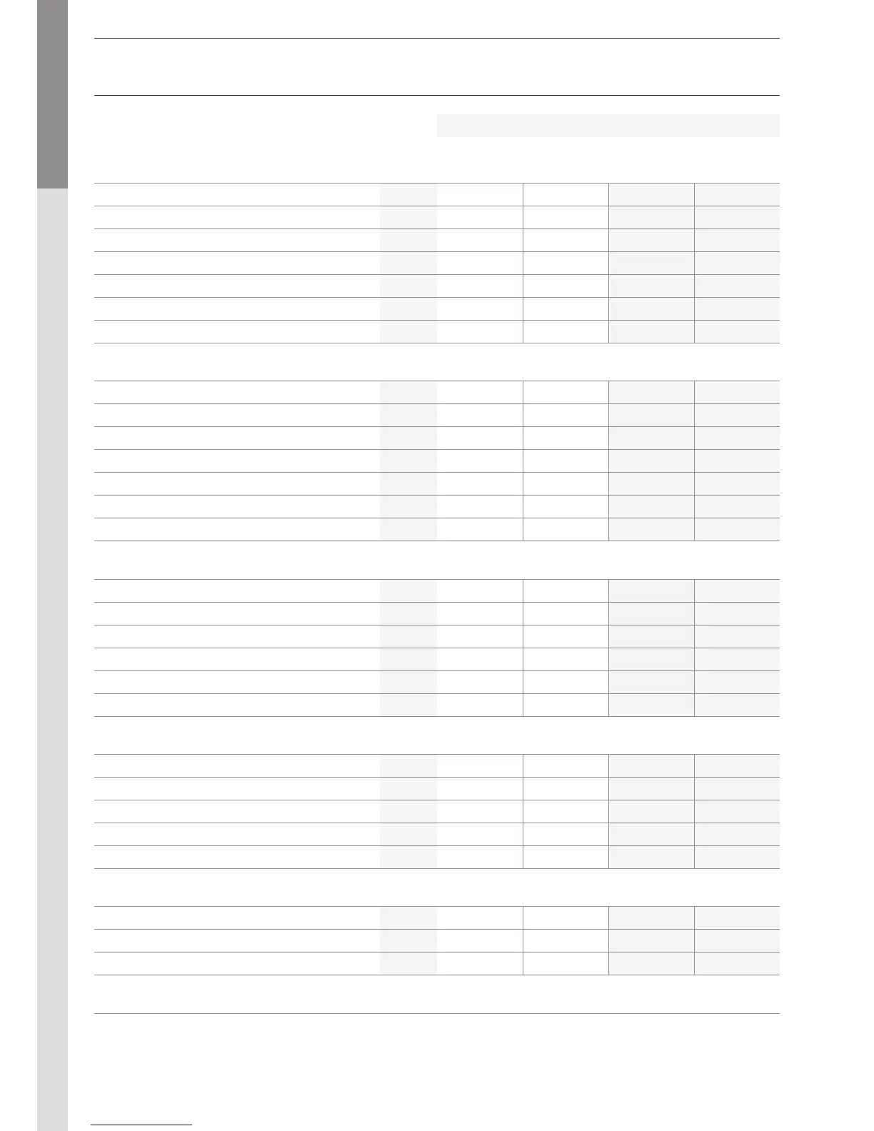
TECHNICAL CHARACTERISTICS
G20
20 mbar
G25
25 mbar
G30
28-30-50 mbar
G31
30-37-50 mbar
Max. rated heat input
kW
80 - 120 80 - 120 80 - 126 80 - 126
Min. rated heat input
kW
22 22 31 31
Max. output 80/60°C
kW
78,1 - 116,6 78,1 - 116,6 78,1 - 122,4 78,1 - 122,4
Min. output 80/60°C
kW
21,6 21,6 30,4 30,4
Max. output 50/30°C
kW
84,8 - 127,2 84,8 - 127,2 84,8 - 133 84,8 - 133
Min. output
50/30°C
kW
23,5 23,5 33,2 33,2
Efficiency at 30% load [EN677]
%
108 108 108 108
CO emission (max / min output power)
mg/kWh
77 - 2 77 - 2 100 - 5 100 - 5
NOx emissions
[max / min output power]
mg/kWh
70 - 26 70 - 26 80 - 30 80 - 30
Flue gas temperature - Max output power 80/60°C
°C
83 83 81 81
Flue gas temperature - Max. output power 50/30°C
°C
65 65 63 63
Mass flow rate of combustion products
kg/h
114 - 171 114 - 171 120 - 190 120 - 190
Flue-gas duct - max. pressure drop
Pa
150 150 150 150
Concentric flue gas channel max length Ø 100 / 150 mm
m
NA NA NA NA
Max rated gas flow rate
m
3
/h
8,5 - 12,7 9,8 - 14,4 2,5 - 3,9 3,3 - 5,1
Min. rated gas flow rate
m
3
/h
2,32 2,74 0,96 1,24
CO
2
[max output power] (with front panel closed)
% CO
2
9 9 10,3 10,3
CO
2
[max power] (with front panel open)
% CO
2
8,8 8,8 10,1 10,1
CO
2
[min power] (with front panel closed)
% CO
2
8,5 - 9,5 8,5 - 9,5 10 - 10,5 10 - 10,5
Gas connection (male)
Ø
1" 1" 1" 1"
Max operating temperature
°C
90 90 90 90
Heating circuit capacity
L
28 28 28 28
Max operating temperature of the heating circuit
bar
4 4 4 4
Heat exchanger pressure drop [∆T = 20°C]
mbar
80 80 85 85
Heating connection (male)
Ø
1"1/2 1"1/2 1"1/2 1"1/2
Class
IP
30 30 30 30
Supply voltage
V/Hz
230 / 50 230 / 50 230 / 50 230 / 50
Maximum absorbed electrical power
A
1,1 1,1 1,1 1,1
kg 83 83 83 83