EasyManua.ls Logo

Prestige APS-997C User Manual

Prestige APS-997C
28 pages
To Next Page IconTo Next Page
Page #1 background imageLoading...
Page #1 background image
128-8775
1 of 28
1
Model APS-997C
Installation Manual
SELECTABLE FEATURES
The selectable features can be set manually as explained below, or with the RF feature programmer.
To set features using the RF programmer, follow the instructions packaged with the programmer.
Factory default settings are indicated by bold text.
NOTE : The method of manual override can either be selected to operate from the valet switch or operate as custom code.
Be certain to place a check mark indicating the method used in the box located on the last page of the owner's manual.
NOTE: Keyless Entry Models with no horn output will Flash the Parking Lights instead of chirp where chirp is indicated.
Also, No data will be indicated if a feature is not available for a particular model. The unit will enter the feature but no selection will be available.
RF Programmable Feature Bank 1 Is For Transmitter Programming See Transmitter Programming Guide.
RF Programmable Features Bank 2 Is Alarm Selectable Features:
Feature Selection 1 Chirp 2 Chirps 3 Chirps 4 Chirps 5 Chirps 6 Chirps
1st DoorL/UL 1 Sec. 3.5 Sec. 1 Sec L, Dbl. U/L Dbl L, 1 Sec UL Dbl L, Dbl UL 1 S l/350mS ul
2nd Accy Lock Auto Lock On Auto Lock Off
3rd Accy. UL Auto UL Dr. Auto UL All Auto UL Off
4th Headlights On Arm On Disarm On Both Off
5th Passive Locks Passive Active
6th Pass/Act Arm Passive Arm Active Arm
7th Siren/Horn Siren/Horn Siren Only Horn Only
8th Horn Chirp 10mS 16mS 30mS 40mS 50mS
9th O/R Method Custom Code Valet
10th 2 Step U/L On Off
11th Chp Del Tx On Off
12th Volts/HdWire Not Available
13th Trigger Circuits All On Doors Off Hood/Trunk Off All Off
14th L/UL Poll Not Available
15th Aux Ch 5 Sel Pulse Push & Hold 10 Sec 20 Sec Latch On/Off Hold 3/S For O/P
16th Aux Ch 6 Sel Pulse Push & Hold 10 Sec 20 Sec Latch On/Off Hold 3/S For O/P
17th Aux Ch 7 Sel Pulse Push & Hold 10 Sec 20 Sec Latch On/Off Hold 3/S For O/P
18th Trigger Delay Not Available
When using the RF programmer, enter the program mode as follows:
Turn the ignition on
Press and release valet switch 3 times
turn ignition off then on
Press and hold valet switch for 5 seconds
Siren chirps 2 times indicating access to RF feature program mode.
Question and Answer IconNeed help?

Do you have a question about the Prestige APS-997C and is the answer not in the manual?

Prestige APS-997C Specifications

General IconGeneral
BrandPrestige
ModelAPS-997C
CategoryCar Alarm
LanguageEnglish

Summary

Selectable Features

RF Programmable Feature Bank 1

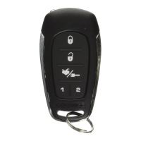
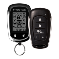
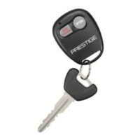
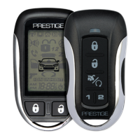
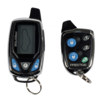
For transmitter programming.

RF Programmable Features Bank 2

Alarm selectable features.

Remote Start Selectable Features

Feature Selection

List of selectable features for remote start.

Installation of Major Components

Control Module

Location and mounting guidelines for the control module.

Siren

Location and mounting guidelines for the siren.

Hood Pin Switch

Installation and purpose of the hood pin switch.

Additional Installation Components

Push-Button/LED/Receiver/Antenna Assembly

Mounting and routing the antenna assembly.

Shock Sensor

Mounting and connecting the shock sensor.

Starter Inhibit Relay

Mounting and wiring the starter inhibit relay.

6-Pin Main Power Harness Wiring

Fused Red w/ White Trace Wire

Connects to +12 volt battery source for control circuit.

Fused Red Wire

Connects to +12 volt battery source for start/accessory relays.

Ignition and Starter Wiring

Yellow Wire: Starter Output

Connects to the starter solenoid wire for engine cranking.

Blue Wire: Ignition 1 Output

Connects to the ignition 1 wire for power to ignition relays.

4-Pin Alternate Ignition Harness Wiring

Orange/Black Wire: Parking Brake Input

Input for turbo timer to ensure parking brake is applied.

Red/Black Wire: + 12 Volts Input

Connects to a constant +12 volt source for additional ignition output.

Pink Wire: Additional Ignition Output

Provides additional +12 volt ignition output.

Multi-Pin Accessory/Input-Output Harness Wiring

White w/ Red Trace Wire: Parking Light Flasher Feed

Connects to parking light flasher relay for light control.

White Wire: Parking Light Flasher Output

Connects to vehicle parking light feed wire.

White w/ Black Trace Wire: Siren Output

Connects to the siren for audible alarm output.

Siren and Trigger Input Wiring

Purple Wire: Door Trigger Input

Connects to vehicle's door courtesy light switches.

Dark Green Wire: Instant Trigger Input

Connects to hood and trunk pin switches.

Light Blue Wire: Ground Output While Running

Provides ground output during remote start operation.

Shock Sensor Bypass and Ignition Outputs

Shock Sensor By Pass

Bypass shock sensor during remote start to prevent false triggers.

Additional Ignition Output

Provides an extra ignition output for vehicles with multiple ignition wires.

GM VATS Key Override

Bypasses GM VATS system for remote start operation.

Entry Illumination and Safety Shut Down Wiring

Entry Illumination Detail

Wiring for interior entry lighting control.

Gray w/ Black Trace Wire: Negative Inhibit Input

Connects to hood pin switch for safety shut down.

Orange Wire: Ground When Armed Output

Controls starter inhibit relay when alarm is armed.

Starter Inhibit and Brake Switch Wiring

Starter Inhibit Wiring Detail

Details wiring for the starter inhibit relay.

Brown w/ Black Trace Wire: Positive Inhibit Input

Connects to brake switch for shutdown when brake is applied.

Black Wire: Chassis Ground Source

Connects to a chassis ground for system operation.

Tachometer Input and Door Trigger Wiring

Green w/ Orange Trace Wire: Tachometer Input Signal

Monitors engine tach rate for remote start operation.

Brown Wire: Negative Door Trigger

Connects to negative output of door pin switches.

Dark Blue Wire: Delayed 300mA Pulsed Channel 3 Output

Provides pulsed output for trunk release or other functions.

Channel Outputs and Trigger Inputs

Channel 3 Relay Wiring Detail

Wiring diagram for channel 3 relay control.

Green w/ Black Trace Wire: Channel 4 Output

Provides 300mA latched output for channel 4.

Dark Blue/Black Trace Wire: External Trigger Input

Allows activation from an external source.

Auxiliary Output Harness Wiring

Instant Trigger Zone 1

Connects to optional triggering devices for zone 1 input.

DELAYED 300 mA PULSED OUTPUT / CHANNEL 5

Provides delayed pulsed output for channel 5.

DELAYED 300 mA PULSED OUTPUT / CHANNEL 6

Provides delayed pulsed output for channel 6.

Transponder Control and Module Connections

2 Pin Transponder Control Output

Controls transponder bypass interface module or relay.

4 Pin Upgrade Telematic Module

Connects to Audiovox data bus interface modules.

3 Pin Door Lock/Unlock Harness

Provides pulsed ground or +12 volt output for door locks.

Door Lock Circuit Configurations

3 Wire Ground Switched Door Lock Circuits

Uses ground pulses for door lock/unlock control.

3 Wire Positive Switched Door Locks

Uses positive pulses for door lock/unlock control.

3 Wire Ground Switched 2 Step Door Locks

Provides 2-step ground unlock for driver's door.

Advanced 2-Step Door Lock Wiring

3 Wire Positive Switched 2-Step Door Locks

Wiring for positive switched 2-step door unlock.

Red/Black Wire Functionality

Controls second step unlock using pulse ground output.

Timed Start Program and Operation

Timed Start Program

Program the automatic start interval (2 or 4 hours).

Timed Start Operation

How to initiate and cancel the timed start mode.

Temperature Start and Tach Programming

Temperature Start

Activates remote start based on vehicle temperature.

Programming Tach Rate

Learn the engine's tach rate for proper operation.

Diagnostics

View diagnostic codes for remote start shutdowns.

Installation Testing and Safety Features

Hood Pin Safety Shut Down Test

Verifies the hood pin switch prevents remote start activation.

Manual Shut Down / Enable Circuit

Allows disabling the remote start unit manually.

Neutral Start Safety Test and Considerations

Neutral Start Safety Test

Ensures vehicle cannot start in gear without proper connections.

Mechanical Neutral Safety Switch Considerations

Addresses safety wiring for mechanical neutral safety switches.

Key In Sensor Circuits

Alternative safety circuits for key-in-ignition detection.

Key In Sensor Circuit Methods

Method 1

Connects drivers door pin switch to key-in sensor switch.

Method 2

Connects key-in sensor switch to safety shutdown wire.

Vehicle Data Bus Port (IDB Port)

4 Pin In Vehicle Data Bus Port

Connects to proprietary Audiovox data bus interface modules.

Completing the Installation

Dome Light Delay Learning

Unit learns vehicle's dome light delay time for smooth operation.

Related product manuals