EN • 12
ENGLISHFRANCAISNEDERLANDSESpAñoLITALIANoDEuTSCH
664Y2300.C
(1Pascal = 0,01 mbar)
Pipe
concentric
Ø 80/125
mm
Air inlet
separate
Ø 80
mm
Air extraction
separate
Ø 80
mm
1 m straight pipe
5.0 1.5 2.0
Pipe with a monitoring
section
2.5 — 1.0
90° pipe bend
6.0 1.9 3.4
45° pipe bend
4.0 1.3 2.3
Vertical pipe
20.0 — —
Horizontal pipe
15.0 — —
This table is based on the equipment offered by ACV and cannot be
applied generally.
INSTALLATIoN
CONNECTION TO THE CHIMNEY
- The chimney connections must comply with the applicable
standards (in Belgium: NBN D51-003), the local energy
supplier’s instructions, the fire regulation and neighbourhood
good practices.
- The Prestige has an inbuilt gas/air ratio regulator, which makes
it largely independent of the pressure drop in the air intake and
flue gas extraction system. However, the maximum pressure
drop for this system may not be exceeded, or the pressure will
diminish. Nevertheless, the gas/air ratio regulator continuously
guarantees optimum combustion with very low emission levels.
- The horizontal flue gas pipes must always be installed with a
min. slope of 5 mm per meter, upwards from the boiler side.
- There must be no obstruction or openings for any other appli-
ances within a radius of 0.5 metres around the flue terminal of
the Prestige.
- You can use the
following table as the basis for calculating this value
(please also
refer to the specimen calculation presented under the table).
- The C33s configuration enables airtight operation in a
pre-existing chimney. The combustion air crosses the space
between the tubing and the pre-existing chimney. Make sure to
clean the pre-existing chimney thoroughly prior to installation,
especially if there is soot or tar residue. Make sure that there
is a clearance area for the combustion air at least equivalent to
the area that would have been provided by separate concentric
ducts or air intake ducts.
: Connection to an exhaust duct venting the combustion
products outside of the installation area, with the
combustion air being drawn directly from this area.
: Connection to an exhaust system of the combustion
products designed to operate with positive pressure.
C13 : Connection by pipes with horizontal terminal units that
simultaneously intake the combustion air and discharge
the combustion products outside through openings that
are either concentric or close enough together to be
subjected to similar wind conditions.
C33 : Connection by pipes with vertical terminal units that
simultaneously intake fresh air and discharge the
combustion products outside through openings that
are either concentric or close enough together to be
subjected to similar wind conditions.
C33s : Connection with an individual system of which the exhaust
duct for the combustion products is installed in an
exhaust pipe that is part of the building. The appliance,
the exhaust duct and the terminal units are certified as
an assembly that cannot be dissociated.
C43 : Connection by two ducts to a collective duct system
serving more than one appliance; this system of collective
ducts features two ducts connected to a terminal unit
that simultaneously intakes fresh combustion air and
discharges the combustion products outside through
openings that are either concentric or close enough
together to be subjected to similar wind conditions.
C53 : Connection to separate ducts for the supply of combustion
air and for venting the combustion products; these ducts
may end in zones with different pressure levels.
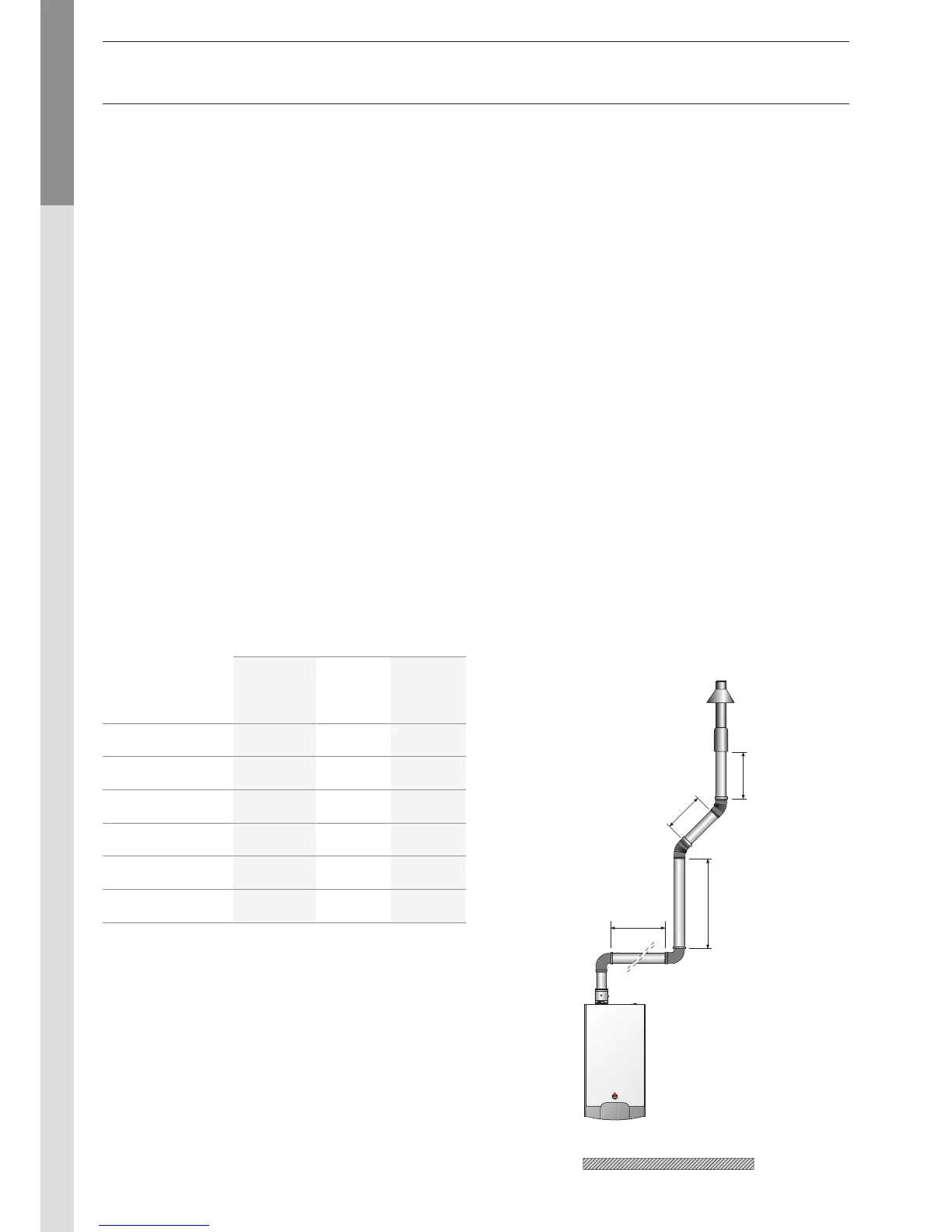
The diagram below consists of the following parts: pipe with
monitoring section + 2 x 90° pipe bends + 2 metres of
horizontal pipe + 2 x 45° pipe bends + (2 + 1 + 1) metres of
vertical pipe and fall back + discharge.
Therefore, the resistance of this system is as follows: