32
Copyright © 2004 CBTricks.com
Pride DX300 CHAPTER 3
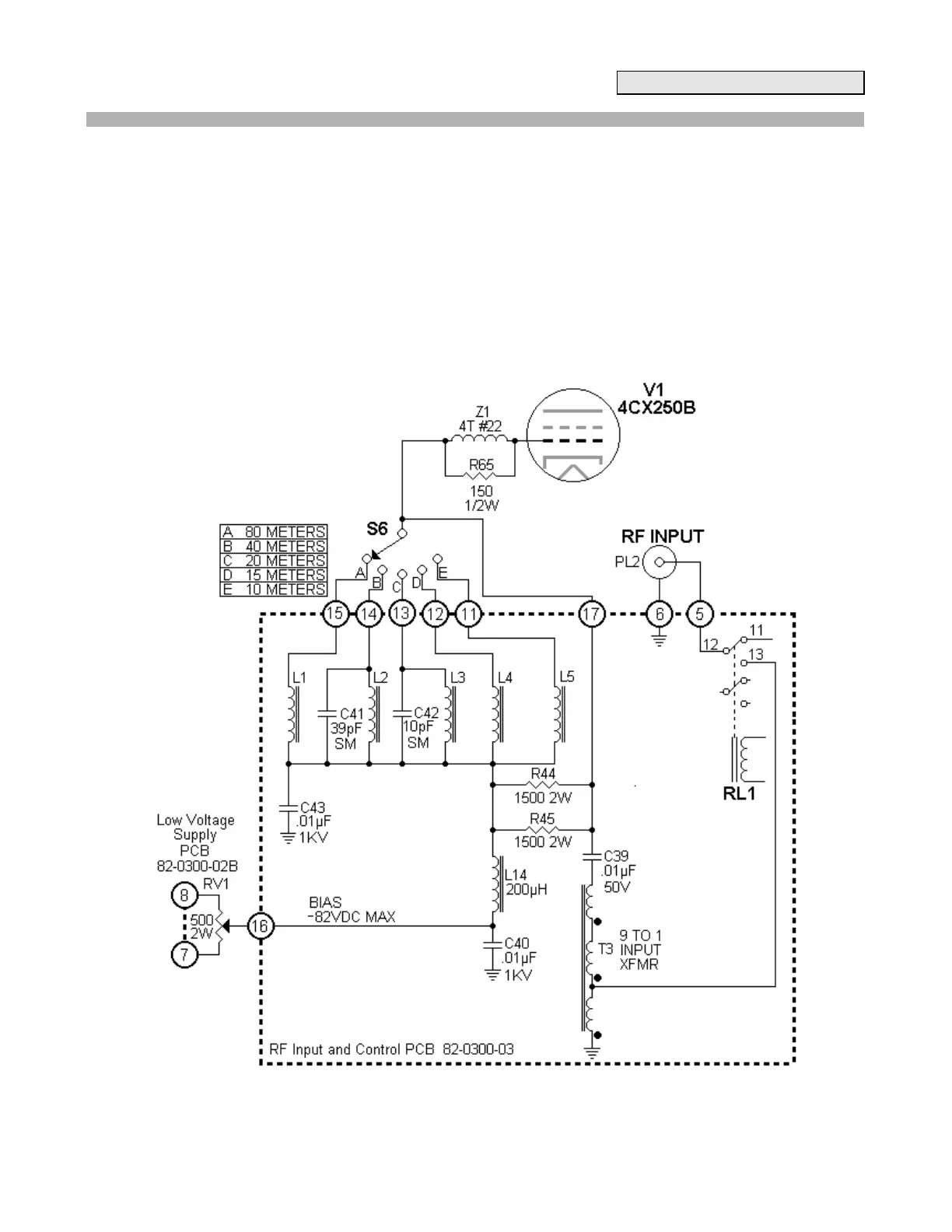
3.4 R.F. Input and Control Board:
This board is located under chassis near the tube socket, and is mounted horizontally. It contains the R.F.
switching circuitry, input matching transformer and tuned toroid input coils, the receiver preamp, and some of the
control circuitry.
Control
Drive power from the exciter is fed to one set of contacts on the (RL1) 4PDT relay and coupled also to a 2N2905
(Q1) relay-switching transistor. When the amplifier is in the standby mode, drive is fed through the relay to the
output connector. In the operate or tune mode, drive is switched to the 9:1 input matching transformer (T3),
which steps the impedance up from 50ohm to 450ohm to feed the input circuitry. The rear deck of the Band
Switch selects a tuned circuit for the appropriate band. Two 1500ohm, 2W resistors (R44, R45) are in parallel
with the resonant input circuit to provide proper loading and bandwidth. Adjustable bias voltage is fed to the grid
through a 200uH choke (L14), an input toroid, and the parasitic choke (Z1) on the tube grid connection.
Figure 3-4 RF Input Circuit