540889_PUB_DATE_1_JUL_2011.DOC INSTALLATION, MAINTENANCE AND USER' MANUAL 27
Installation
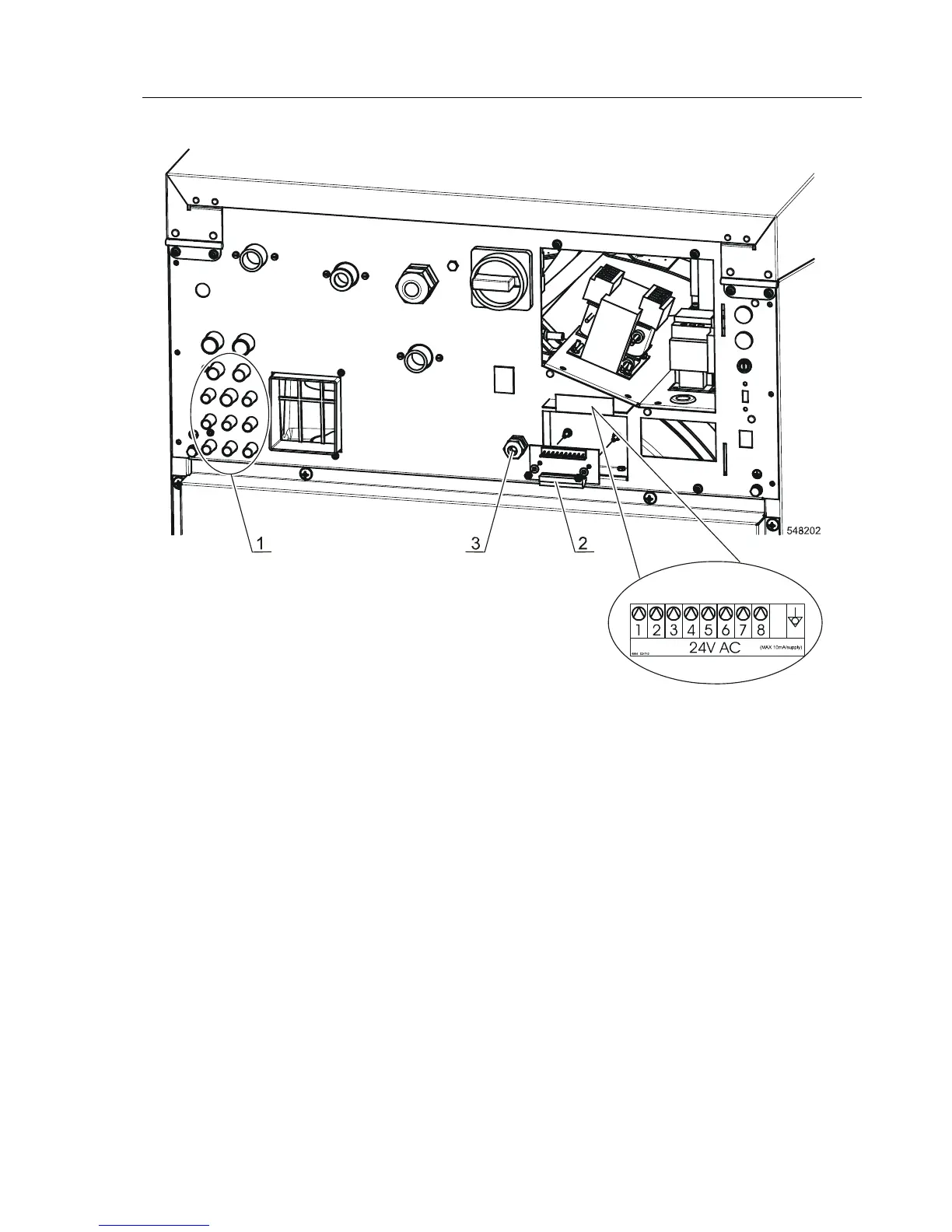
Fig.10
Electrical connection
The power supply of the liquid soap supply system has to be connected to an external electrical source. Only
authorized workers with a valid qualification must execute the electrical connection on the machine according
to the valid local standards. The correct connection way can be found on the wiring diagram that is located
inside the cabinet in a plastic bag. Do not connect the liquid soap pump system in the washer.
Electronic controller with blue pcb and graphical display
For electric connection of supply control signals is available on the back side of the machine the terminal box
with LED signalization of activation of the respective pump, (see fig.10., pos.2). Above the terminal box there
is a label for electric connection, fig.10. Detail connection of signals could be also found on the electric
scheme of the machine. Signals for supply pumps control are 24V AC. Maximum current for control circuits of
pumps must be limited to 10mA. Lead the cable for connection of pumps control signals through the plastic
cable bushing, pos.3. After connection of conductors to the respective positions of the connector “P” (screw
clamps), fix up the cable by tightening the cable bushing) against disconnection and close the box with the
cover. For details about liquid soap supply system programming, see Programming manual.
Electrical connection label