12
8
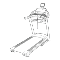
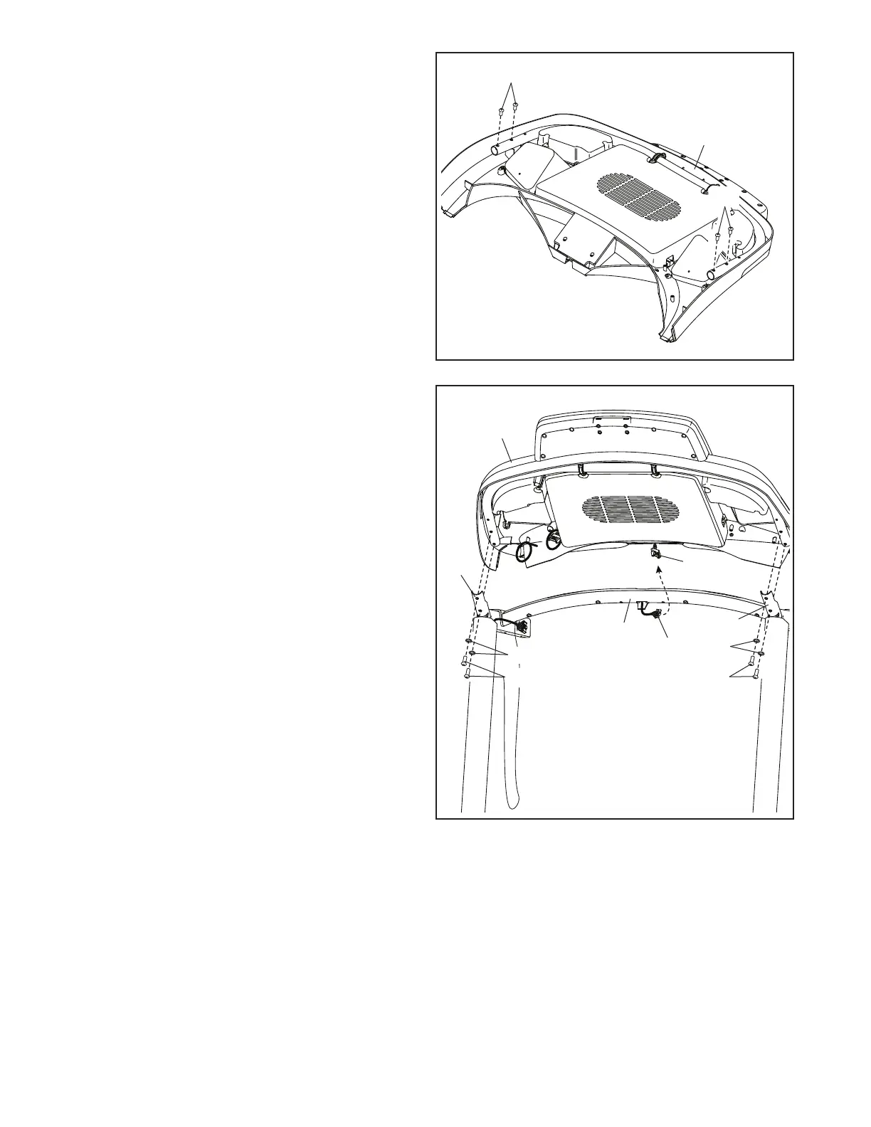
8. Set the console assembly (F) face down on a
soft surface to avoid scratching the console
assembly. Remove and save the four 1/4" x
1/2" Screws (12).
12
F
12
9
F
93
86
18
12
12
18
H
G
9. Hold the console assembly (F) near the Pulse
Crossbar (93).
See the inset drawing. Connect the pulse wires
(G, H). The connectors should slide together
easily and snap into place. If they do not, turn
one connector and try again.
Next, set the console assembly (F) on the brack-
ets on the Handrails (86); do not pinch any
wires. Insert the wires (G, H) into the console
assembly.
Attach the console assembly (F) with the four
1/4" x 1/2" Screws (12) that you removed in step
8 and four 1/4" Star Washers (18); do not fully
tighten the Screws yet.
86