V1.0 PROCUT 30A Digi Plus Plasma Cutter 9085754
Visit www.princessauto.com for more information 23
TORCH TIP HEIGHT & POSITION
The distance and position of the plasma torch cutting tip has an effect on the
quality of the cut and the extent of the cut’s bevel. The easiest way to reduce
bevel is by cutting at the proper speed and height for the material and
amperage that is being cut.
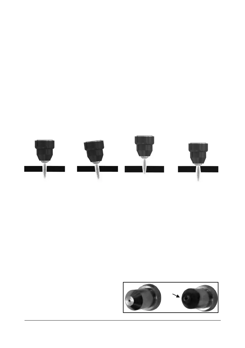
1. Correct torch height and square to the material. Minimum bevel &
equal bevel. Longest consumable life (Fig. 9).
2. Torch angled to the material. Unequal bevel, one side may be
excessively beveled (Fig. 10).
3. Torch height too high. Excessive bevel, plasma stream may not cut all
the way through the material (Fig. 11).
4. Torch height too low. Reverse bevel. Tip may contact the work and
short out or damage the tip (Fig. 12).
CUTTING NOZZLE TIP SIZE AND CONDITION
The cutting nozzle’s orifice focuses the plasma stream. It is important to use the
correct size tip for the amperage being used.
The size of the orifice dictates the width of the plasma stream. The low-amp
nozzle has a smaller orifice which maintains a narrow plasma stream at lower
settings for use on thin-gauge material.
A low-amp nozzle used with a high amperage setting will distort and damage
the nozzle beyond use. A high amperage nozzle used with lower amperage
will prevent the plasma stream from focusing correctly and create a wider cut
than intended.
The nozzle condition is critical to the quality of the cut result. A worn or
damaged nozzle orifice will produce a distorted plasma stream, resulting in a
poor cut quality (Fig. 13-1).
It is recommended to use a 3/64
in. tip with a setting of 0 to 40
amps and a 1/16 in. tip with a
setting of 40 to 80 amps.