Validating the Cable's Shield and Continuity Test
DANGER
• Remove the battery door and disconnect the battery from the Probe.
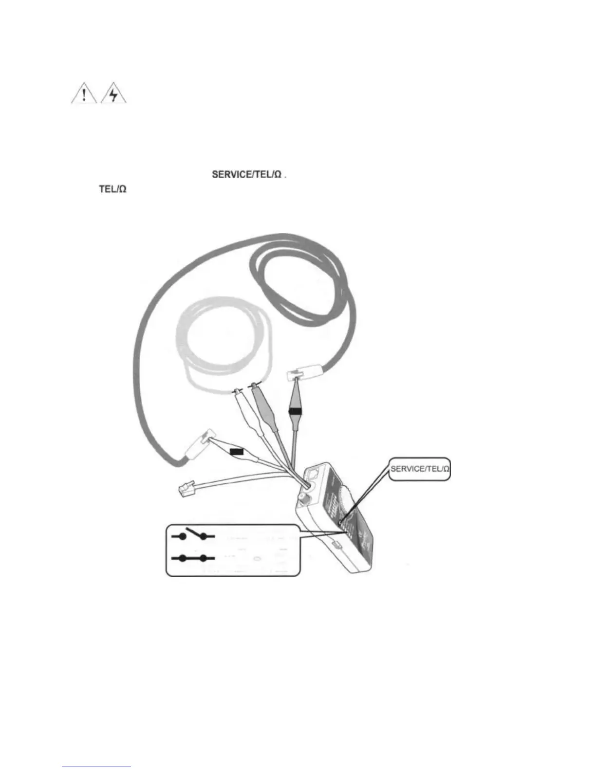
To validate cable shield during cable map tests, do the following as shown in Figure 8:
1. Connect the Toner to the circuit as shown in Figure 8. Connect the test leads to the telephone punch-down
blocks, RJ11, and RJ45 jacks.
2. Turn the Toner's rotary switch to
3. The LEDs of the Toner indicates the status as below:
Green light: cable shielded and connected (Resistance<300D).
No light: no shield and no service (Resistance>300D).
Figure 8 Continuity Test
13
Testing for
Continuity
Validating the
Cable's Shield
= TEL/Ù ï No Light
Open: Resistance
>300Ù
= TEL/ Ù Green
Short: Resistance <
300Ù
OR
OR