©2022 Pro-Vision Solutions, LLC. Page 20 of 56
Analog HD Heavy Duty Camera Installation
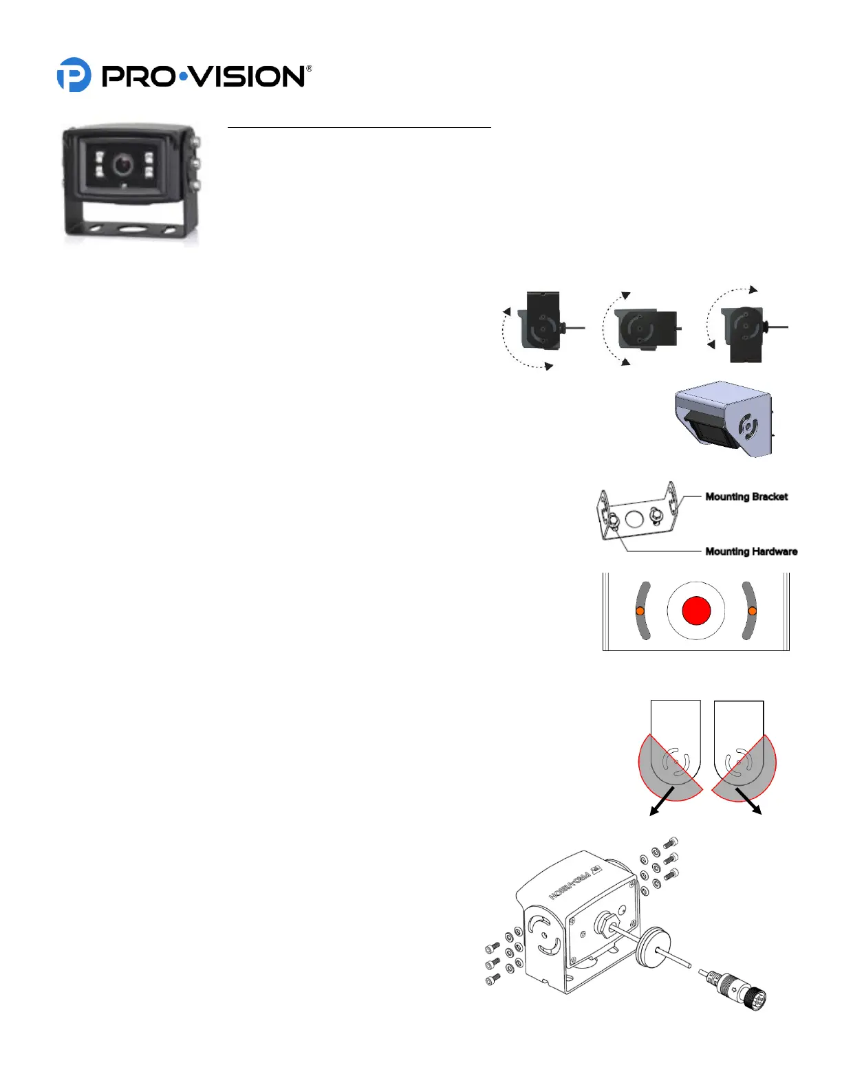
The AHD Heavy Duty Camera (Kit P/N: DVR-916, Camera P/N: PC-1916) is designed to be
mounted in the rear of the vehicle. It is small, allowing it to be mounted at the top of the rear
for easier wiring and better field of view. The camera bracket allows for mounting above,
below, or directly to the mounting surface. The camera has four (4) infrared (IR) LED’s that
provide illumination during low light/dark conditions. The camera has a waterproof, built-in
microphone. The camera lens has a wide 110° horizontal and 60° vertical coverage. The
camera also has an optional heavy-duty mounting (P/N: PC-1271) for applications where the
camera is mounted in an area that requires additional protection from damage.
Mounting Location:
This camera is often used on the outside rear of heavy-duty vehicles
like box trucks, van trailers, and fire trucks to provide video capture of
backup incidents and observation behind the vehicle. When using the
U-Bracket, the camera can only be mounted to a horizontal surface, it
can be mounted above, below, or directly to the mounting surface and can adjust up to 180°. The
camera mounting screw holes are slotted to allow the camera to be aimed left or right after
mounting. The Heavy-Duty Bracket is designed for vertical mounting. It offers greater protection
from heavy debris and covers the camera from the top and sides.
Standard Installation:
1. Locate the desired mounting location of the camera. It is recommended to
power on the DVR unit and temporarily connect the camera to it and
observe that the view in the desired mounting location is satisfactory before
proceeding to the next step.
2. When the desired mounting location is found, mark or measure the two (2)
mounting screw hole locations in the bracket (shown in ORANGE at right). If
necessary, remove the camera from the bracket.
3. If the cable will be routed through the vehicle body, it is often routed through a
3/4” holed drilled directly in the center of the vehicle body behind the bracket
(shown in RED color above). Mark and drill this hole if needed. Remove any
burrs from the hole to prevent damage to the cable.
4. Install the camera bracket to the marked locations from step 3 (shown in ORANGE
above). Ensure the bracket is oriented for properly aim as shown in the image above
right, if needed flip the bracket 180° to allow proper adjustment.
5. Install the camera into the bracket with the six (6) screws, metal washers, and nylon
washers as shown at right. Leave the screws slightly loose until final camera aim
adjustment is completed.
6. Route the camera cable through the mounting hole in the
center of the bracket (if applicable) and install a grommet or
put adhesive around the cable to provide a seal with the
hole.
7. Route and install the extension cable(s) to the cameras final
mounting location and connect it to the camera. Leave
enough slack to allow removal of the camera if necessary for
service in the future (typically 4”-6”).
 Loading...