©2022 Pro-Vision Solutions, LLC. Page 3 of 56
INSTALLATION
Understanding the System
PD-1902 DVR Unit
The Digital Video Recorder (DVR) unit is located inside the locking
cage. To remove the DVR, slide the top of the cage forward slightly
and lift up on the front. The DVR is removed by lifting on the front of
the DVR and sliding it forward.
This device complies with Part 15 of the FCC Rules. Operation is subject to the following two conditions: (1) this device may not cause
harmful interference, and (2) this device must accept any interference received, including interference that may cause undesired operation.
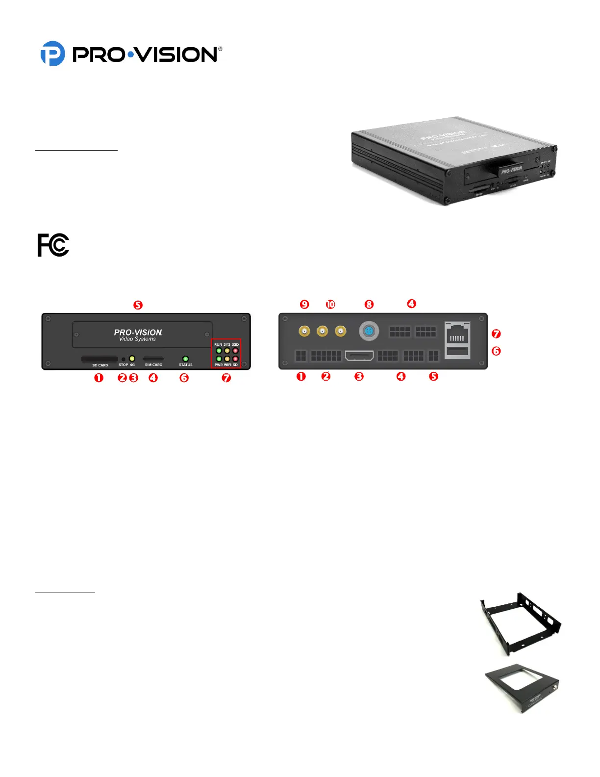
Front of DVR: Rear of DVR:
– SDXC Card Slot – Power Cable Connection
– Record STOP Button – GPS/EVT/Triggers Cable
– 4G Status Indicator – HD A/V Output Connection
– 4G SIM Card Slot – Analog Camera Input Connections
– Solid-State Drive Tray – A/V Output Connection
– System Status Indicator – USB Port
– Operational Status Indicators – LAN Port
– Digital HD Camera Input
– Wi-Fi Antenna Connections
– 4G Antenna Connections
Locking Cage
PD-1808 Locking Cage Base
The locking cage base is used to secure the DVR in whichever mounting position the user
requires. It can be mounted horizontally or vertically, the internal g-force sensor performs best
when mounted near parallel or perpendicular to the ground.
PD-1809 Locking Cage Cover
The locking cage cover completes the DVR cage and allows the user to lock and secure the
DVR from being tampered with.