©2022 Pro-Vision Solutions, LLC. Page 26 of 56
Display Installation
There are multiple different monitors available that installed in the vehicle and connected to the DVR. The DVR unit
includes a standard RCA video output for temporary display connection and aiming.
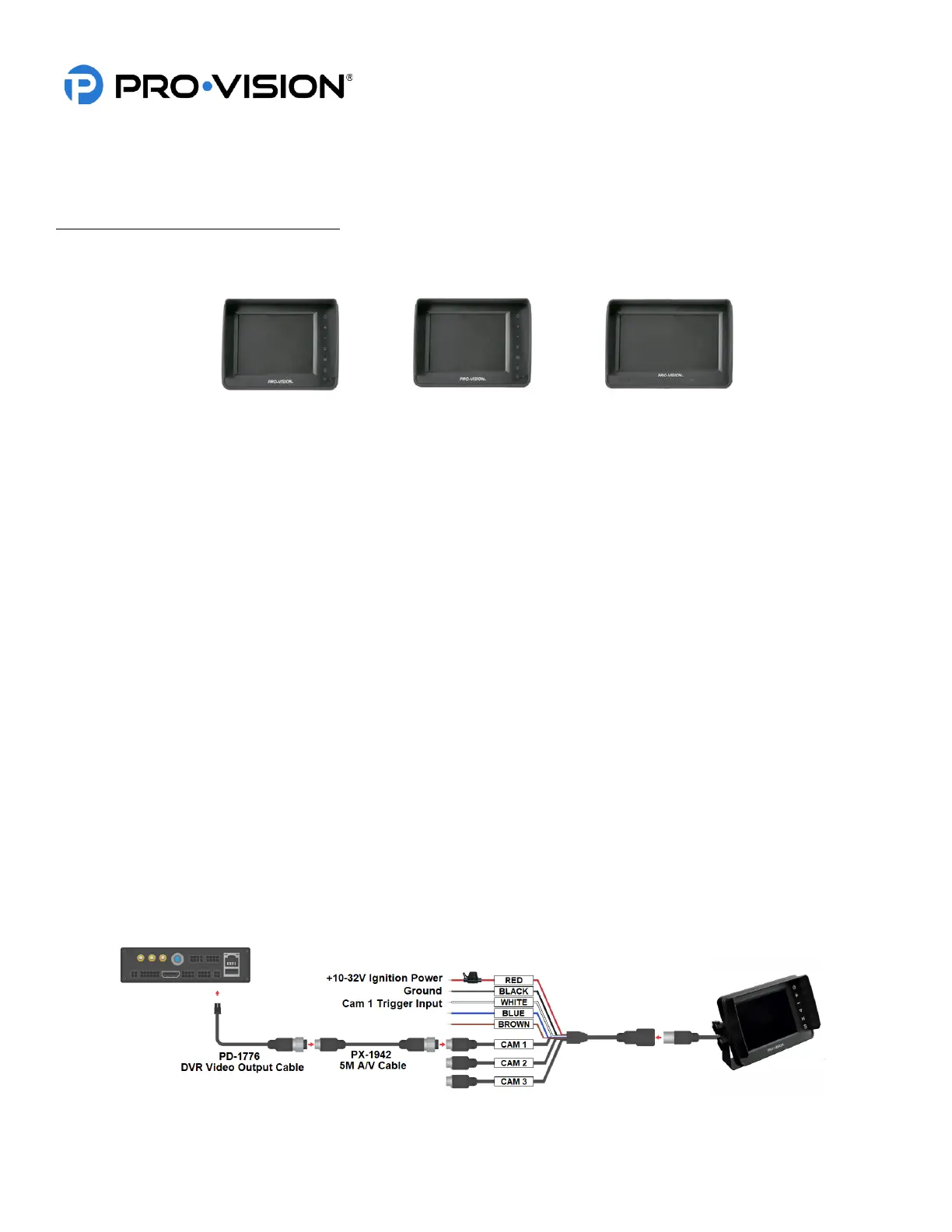
5”, 5” Waterproof, and 7” HD Monitor Kits
The 5” (PM-1950S), 5” Waterproof (PM-1930S), and 7” (PM-1970S) monitors all share the same mounting and installation
instructions; they have the same connections and have similar mounting hardware.
1. Determine monitor mounting location and then decide which mount will be used. The U-shaped mounting bracket
works well mounting to the dash or ceiling. The adjustable fan mounting bracket works well adhesive mounted to
dashboards or windshields, it also can be screw mounted.
2. Use the included mounting hardware and install the mounting bracket. If the adhesive mount is to be used, hold
the mount against the desired location and check to see if it fits well, if there is a curve to the surface, bend the
bracket slightly to match the mounting surface before adhering. Remove the adhesive backing and then firmly
press the mount to the surface and hold for 30 seconds. It is recommended to allow adhesive to cure for 1 hour
prior to attaching monitor.
3. Locate your ignition-controlled power and ground locations in the vehicle. A fused location is not needed as the
power harness for the monitor includes an inline fuse.
4. Make the proper connections to the red and black wires on the power harness to the vehicle power connection as
noted in the diagram below. The green wire is not necessary for this application.
5. Route the power harness large female connector to the mounting location of the monitor.
6. Mount the monitor to the mount and make the connection from the monitor to the monitor power harness. Make
note of the connector alignment arrows making the connection.
7. If the monitor power harness CAM 1 connector is further than 3 ft. from the DVR, use a 5m AV cable to connect
the monitor power harness to the DVR output.
8. Connect the PX-1942 5M A/V cable to the CAM 1 (Camera 1) input of the monitor power harness, then run the
male end to the PD-1776 DVR to Monitor Interface Cable.
9. Connect the CAM 1 Trigger (White) to a triggered power source if it is desired to have the monitor automatically
turn on in when triggered; a trigger connection is not required as the monitor can be manually powered on with
7the power button.
 Loading...