©2022 Pro-Vision Solutions, LLC. Page 29 of 56
System Triggers
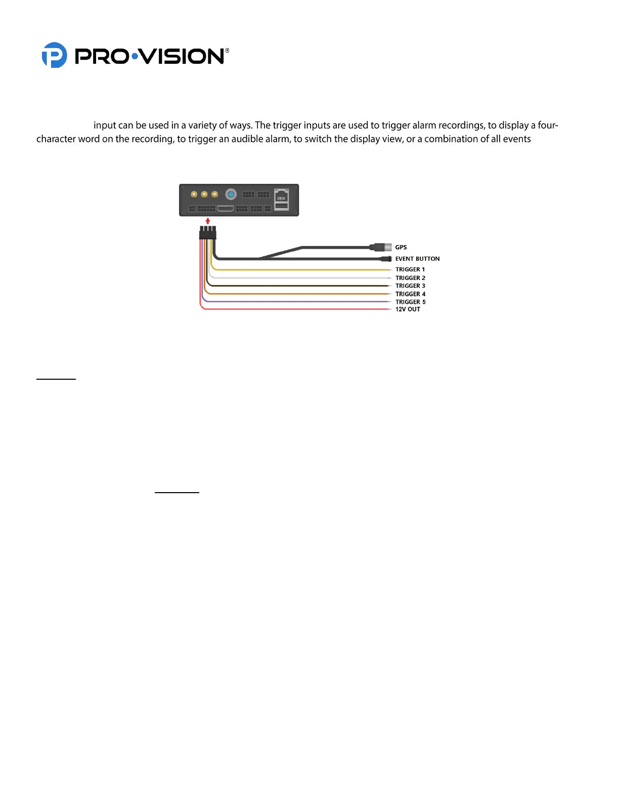
The unit has five (5) auxiliary trigger inputs located on the PD-1835 GPS / Event / Triggers cable at the rear of the unit.
Each trigger
. The unit
also has one (1) trigger output; this output can provide 12VDC (0.1A Max Current) to trigger a relay or other external
function in the vehicle.
How Trigger Inputs Work
The standard setting for the trigger inputs is such that when a 12V signal is sent to a trigger wire, an alarm recording will
be triggered to start, and a corresponding four-character acronym will display on the screen.
Example: When Trigger 1 receives 12V, “T1” will display on the video by default.
When the 12V signal is removed, the four-character word will no longer display on-screen, and the DVR will continue the
alarm recording for a preset amount of time (Post-Event Recording).
Configurable Trigger Input Settings
• Each trigger can be set independently to receive a high-level signal (1V to 24V DC) or a low-level signal
(GROUND).
• Each trigger can be set independently to display any four-character phrase; characters include capital letters A-Z
and numbers 0-9. Examples: “PTO”, “DOOR”, “OHL3”, “BRK4”, “DR11.”
• Each trigger can be set independently to turn alarm recording ON or OFF by camera.
• The Alarm recording can be configured to have Pre-Event Recording of 0-60 seconds. Pre-Event Record Time is
a segment of video prior to the activation of the trigger that will be added to the beginning of the alarm recording.
• The Alarm recording can be set to perform a Post-Event Recording of 0-180 seconds. Post-Event Record Time is
the time that the DVR will continue an alarm recording after a trigger signal has been removed.
Connecting Trigger Input(s)
To connect each trigger input, determine the trigger signal type: 12-24V Signal, the level will be set to “HIGH” (Default),
Ground (-) signal will require the level to be set to “LOW” for the trigger.
After your trigger source has been located, run a wire from the source to the desired trigger input on the
GPS/Event/Trigger Cable.
How the Trigger Output Works
The trigger output is designed to provide power to activate a 3
rd
party or vehicle accessory when a preset scenario on the
DVR occurs. For example, if the excess idling is triggered, it can send a 12V signal to a driver or other vehicle system.
Configurable Trigger Output Settings
The trigger output can be programmed to activate when any trigger input is active or if the vehicle idling alarm is active.
 Loading...