©2022 Pro-Vision Solutions, LLC. Page 30 of 56
Connecting Trigger Output
The trigger output can provide up to 12VDC 0.1A (100mA) to activate an accessory, if a higher current/voltage accessory
is to be used, an appropriate 12V relay must be used to provide the proper current/voltage to the accessory. After your
trigger destination has been located, run a wire from the destination to the “12V TRIGGER OUTPUT on the DVR. This
circuit should be fused to prevent damage to the DVR.
External Event Marker Button
The Event Marker Button (P/N: PD-1770) is used to provide the driver an easy way to mark Normal video as an important
Alarm Video and to serve as a marker to mark a point of importance within an Alarm video. The button also provides the
driver with a clear indicator of the system operation.
Recommended Mounting Locations:
The button should always be mounted within reach of the driver while seated normally and buckled. The LED status light
on the button should be visible either directly or indirectly (reflected off a nearby dash or console) by the driver. If unsure
of the button location or LED brightness it is recommended to temporarily power the DVR unit with the button connected
prior to installing to observe the LED visibility. The buttons are commonly mounted to the dash to the left of the gauge
cluster, to the upper driver’s side corner of the windshield (to the glass) or on the center console.
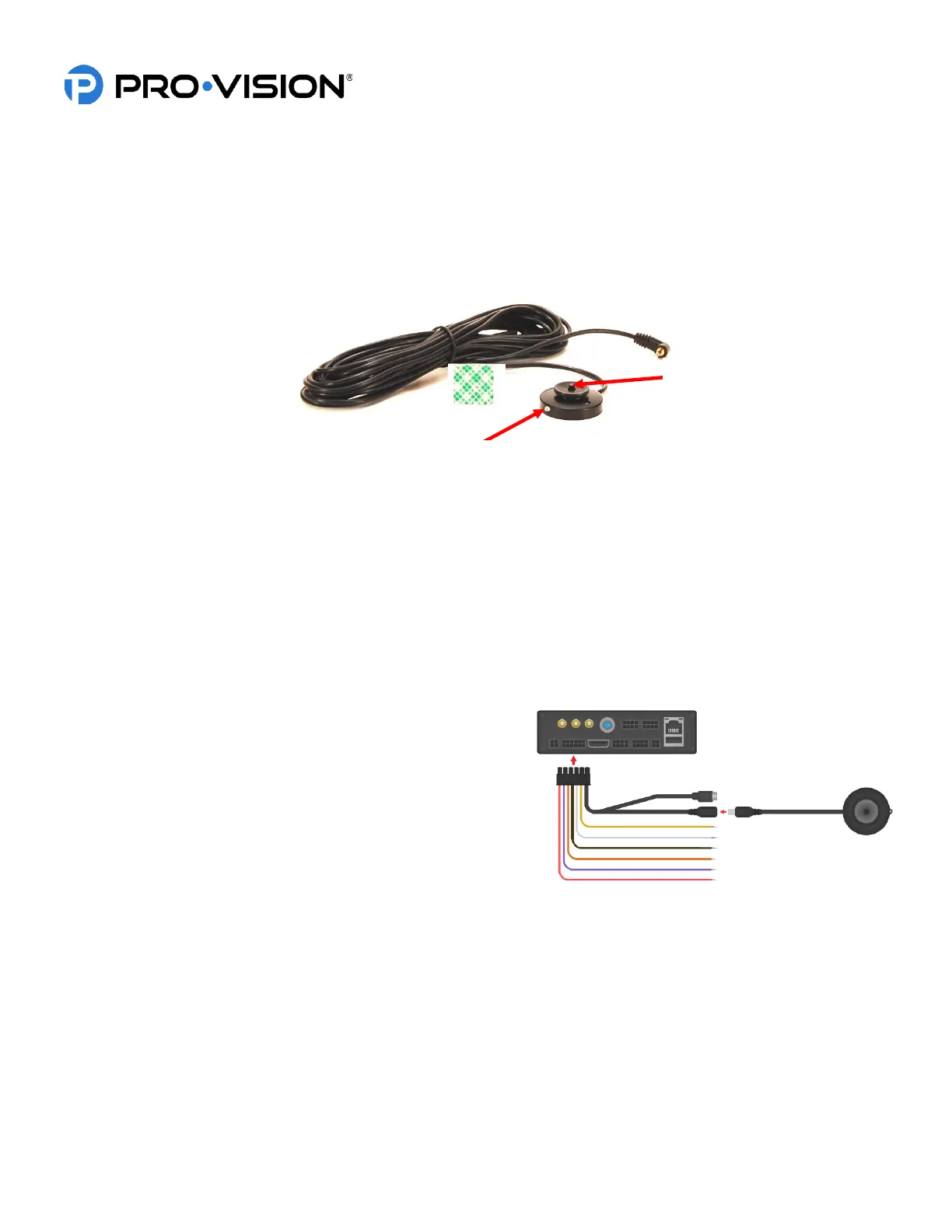
Installation:
The Event Marker Button includes 6m (20 ft.) of cable. This cable
needs to be routed starting from the button location to the PD-
1833 GPS/Event/Trigger Interface Cable at the rear of the DVR.
The button is usually mounted within reach of the driver using the
included adhesive pad. When mounting the button, be sure to
rotate the button so that the LED light faces in the proper direction.
LED Light:
The event marker button LED will begin to flash green while the DVR is booting, once booted and the disk is loaded it will
switch to solid green when it begins recording.
FLASHING GREEN - ON but not recording
SOLID GREEN - Recording normally
FLASHING RED - Not recording due to problem, LED will also momentarily flash red when button is pressed
SOLID RED – Hardware problem/button malfunction
 Loading...