Em.Heat
AutoCool
Set At
On LHM
Tech Set
Set Sched
Next
Run Sched
Set Time
Hold
Done
Menu
Prev
HOLD
STAGES
1+2+3
COOL ON
HEAT ON
FAN ON
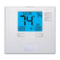
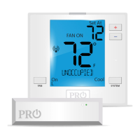
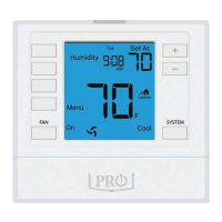
Thermostat Quick Reference
The low battery indicator is displayed when the AA battery power is low. If the user
fails to replace the battery within 21 days, the screen will only show the low battery
indicator but maintain all functionality. If the user fails to replace the batteries after
an additional 21 days (days 22-42 since rst “low battery” display) the setpoints will
change to 55˚F (Heating) and 85˚F (Cooling). If the user adjusts the setpoint away from
either of these, it will hold for 4 hours then return to either 55˚F or 85˚F. After day 63
the batteries must be replaced immediately to avoid freezing or overheating because
the thermostat will shut the unit o until the batteries are changed.
Important
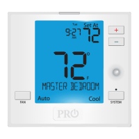
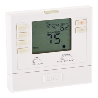
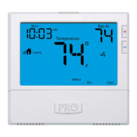
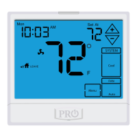
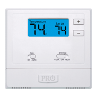
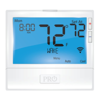
Indicates the current room temperature
Time and day of the week
Setpoint: Displays the selected setpoint temperature.
Hold is displayed when the thermostat program is permanently overridden.
System Operation Indicators:
The COOL ON , HEAT ON or icon will display when the COOL, HEAT, or
(fan) is on. The compressor delay feature is active if these are ashing.
Low Battery Indicator: Replace batteries when this indicator is shown.
Menu Options: Shows dierent options.
Program Time Periods: This thermostat has 4 programmable time periods
per day.
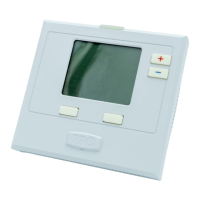
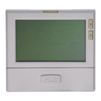
Getting to know your thermostat
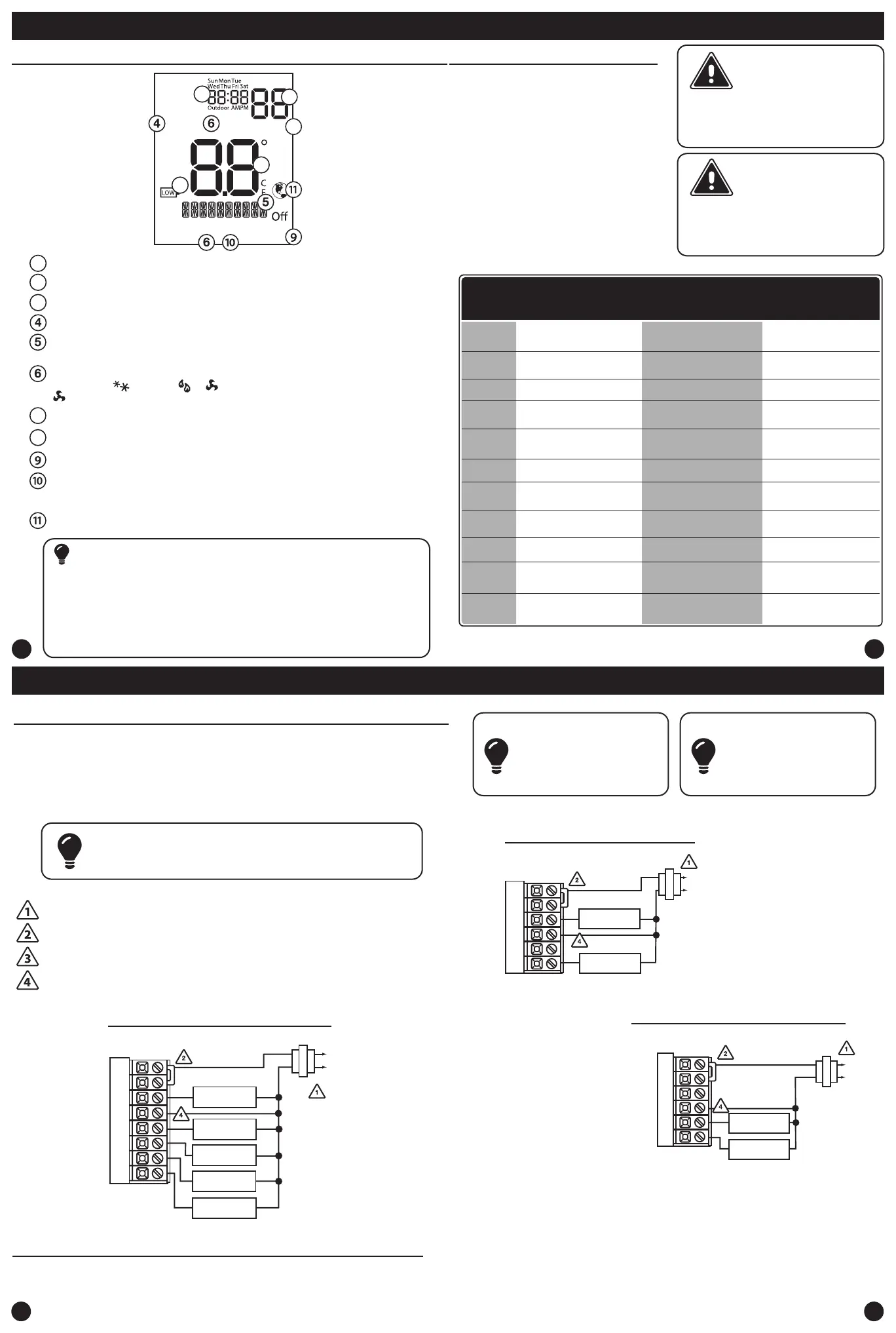
Wiring
5
6
7
8
Wiring Tips
C Terminal
The C (common wire) terminal does
not have to be connected when the
thermostat is powered by batteries.
Wire Specications
Use shielded or non-shielded
18-22 gauge thermostat wire.
Caution:
Electrical Hazard
All components of the control
system and the thermostat
installation must conform to Class II
circuits per the NEC Code.
Warning:
Installation Tip: Do not overtighten terminal block screws, as this
can damage the terminal block. A damaged terminal block can
keep the thermostat from tting on the subbase correctly or cause
system operation issues. Max Torque = 6in-lbs.
Wiring
If you are replacing a thermostat,
make note of the terminal
connections on the thermostat that
is being replaced. In some cases
the wiring connections will not be
color coded. For example, the green
wire may not be connected to the G
terminal.
Loosen the terminal block screws.
Insert wires then retighten terminal
block screws.
Place nonammable insulation into
wall opening to prevent drafts.
1.
2.
3.
Failure to disconnect the power
before beginning to install this
product can cause electrical shock
or equipment damage.
Power supply
Factory - installed jumper. Remove only when installing on a 2 transformer systems.
System: Indicates current mode of operation.
Note: This thermostat is
hardwire powered when the
24V transformer is
connected to the Common
and RC terminals of the
thermostat.
Use either O or B terminals for changeover valve.
Optional 24 VAC common connection when thermostat is used in battery power mode.
Terminal
2 Heat 2 Cool
Conventional
System
2 Heat 2 Cool
Heat Pump
System
3 Heat 2 Cool
Heat Pump
System
RC
RH
C
B
O
G
W/E
W2
Transformer power
(cooling)
Transformer power
(heating)
Transformer common
Energized in heating
Energized in cooling
Fan relay
First stage of heat
Second stage of heat
Transformer power
(cooling)
Transformer power
(heating)
Transformer common
Heat pump changeover
valve energized in heating
Fan relay
First stage of
emergency heat
Auxiliary heat relay,
second stage of heat
Heat pump changeover
valve energized in cooling
Transformer power
(cooling)
Transformer power
(heating)
Transformer common
Heat pump changeover
valve energized in heating
Fan relay
First stage of
emergency heat
Auxiliary heat relay,
third stage of heat
Heat pump changeover
valve energized in cooling
Wiring Diagrams
Stages: Stage 1 will appear on the display when the 1st stage of heat or
cool is on. +2 will appear on the display when the 2nd stage of heat or cool
is on. +3 will appear on the display when the 3rd stage of heat or cool is on.
Y
Y2
First stage of cool
Second stage of cool
First stage of heat & cool
Second stage of cool
First stage of heat & cool
Second stage of cool
& second stage of heat
Note: In many systems
with no emergency heat
relay a jumper can be
used between E and W2.
1
2
3
7
8
1
2
3
7
8
Globe: Globe is displayed if an energy ecient temperature has been selected.
S1/S2
Remote Sensor Remote Sensor Remote Sensor
Typical 2H/2C System: 1 Transformer
Typical Heat Only System With Fan
Typical Cool-Only System With Fan
FAN RELAY
HEAT RELAY
RC
RH
Y
C
W/E
G
C
R
L2
L1(HOT)
FAN RELAY
COMPRESSOR
RELAY
C
R
L2
L1(HOT)
RC
RH
Y
C
G
W/E
RC
RH
Y
C
W/E
G
W2
Y2
COMPRESSOR
RELAY
FAN RELAY
HEAT RELAY 2
COMPRESSOR
RELAY 2
HEAT RELAY
C
R
L2
L1(HOT)
Note:
In many systems with no emergency heat relay a jumper can be installed
between W/E and W2.
Wiring Diagrams
Auto
 Loading...