www.usaprocom.com
9200049-02A
INSTALLATION
FASTENING HEATER TO WALL
Mounting Bracket
The mounting bracket is located on back panel
of heater. It has been taped there for shipping.
Remove mounting bracket from back panel.
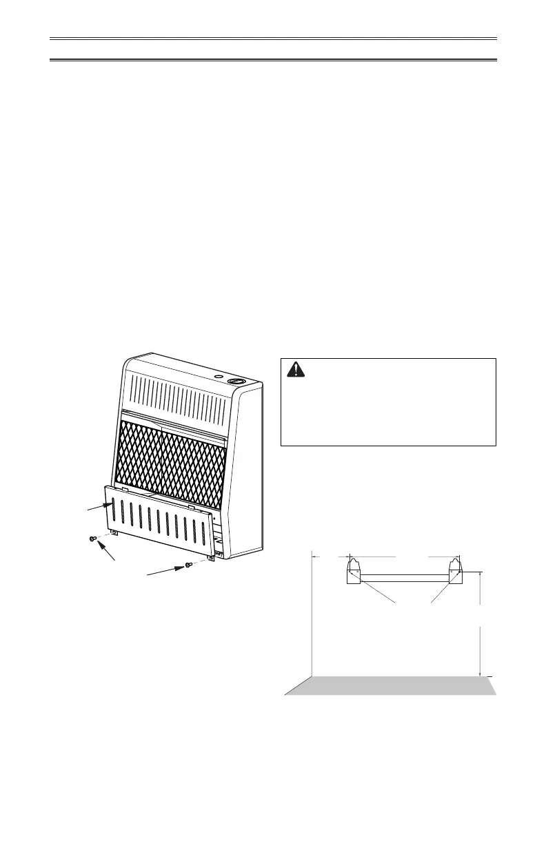
Figure 5 - Removing Front Panel Of
Heater
LOCATING HEATER
This heater is designed to be mounted on a
wall. For convenience and eciency, install
heater:
1. Where there is easy access for operation,
inspection, and service.
2. In the coldest part of room.
When installing the appliance directly on car-
peting, tile or other combustible material other
than wood ooring, the appliance shall be
installed on a metal or wood panel extended
the full width and depth of the appliance.
REMOVING FRONT PANEL OF
HEATER
1. Remove two screws near bottom corners
of lower front panel.
2. Pull bottom of lower front panel forward,
then down (see Figure 5).
Methods For Attaching Mounting
Bracket To Wall
Use only the last hole on each end of mount-
ing bracket to attach bracket to wall. Attach
mounting bracket to a wall only in one of two
ways:
1. Attaching to wall stud: This method pro-
vides the strongest hold. Insert mounting
screws through mounting bracket and into
wall studs.
2. Attaching to wall anchor: This method
allows you to attach mounting bracket to
hollow walls (wall areas between studs)
or to solid walls (concrete or masonry).
Decide which method better suits your needs.
Either method will provide a secure hold for
the mounting bracket.
Marking Screw Locations
1. Tape mounting bracket to wall where
heater will be located. Make sure mount-
ing bracket is level.
WARNING: Maintain minimum
clearances shown in Figure 4,
page 8. If you can, provide greater
clearances from oor and join-
ing wall.
2. Mark screw locations on wall (see Figure
6). Note: Mark only last hole on each end
of mounting bracket. Insert mounting
screws through these holes only.
3. Remove tape and mounting bracket from
wall.
Screw
Front
Panel
Figure 6 - Mounting Bracket Clearances
7
3
/
4
"
Min.
12
1
/
4
"
16"
Min.
Only Insert Mounting
Screws Through Last
Hole On Each End
Adjoining Wall
Non-combustible Flooring or Top of
Combustible Tile Carpeting or Other Material