EasyManua.ls Logo

Procom PCK160VT User Manual

Default Icon
80 pages
To Next Page IconTo Next Page
Page #1 background imageLoading...
Page #1 background image
IMPORTANT: Read and understand this manual before
assembling, starting or servicing heater. Improper use
of heater can cause serious injury. Keep this manual for
future reference.
Never use heater in living or sleeping areas.
Heater is suitable for outdoor use and for use on com-
bustible oors.
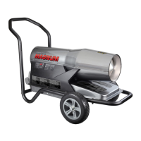
PORTABLE FORCED AIR HEATERS
KEROSENE/DIESEL HEATER WITH BUILT-IN THERMOSTAT
OWNER’S MANUAL
PCK110VT - ADJUSTABLE 80-110,000 BTU/HR
PCK160VT - ADJUSTABLE 110-160,000 BTU/HR
PCK175VT - ADJUSTABLE 125-175,000 BTU/HR
PCK220VT - ADJUSTABLE 160-220,000 BTU/HR
Questions, problems, missing parts? Before returning to your retailer, call
our customer service department at 1-866-573-0674, 7:30 am - 4:15 pm CST,
Monday through Friday or email customerservice@usaprocom.com

Questions and Answers:

Procom PCK160VT Specifications

General IconGeneral
ModelPCK160VT
IgnitionElectronic
TypeKerosene/Diesel
BTU Output160, 000 BTU
Fuel TypeKerosene

Summary

Safety

Unpacking

Assembly

Wheel Assembly

Step-by-step guide for assembling the wheels onto the heater unit.

Handle Assembly

Instructions for attaching the front and rear handles to the heater.

Product Identification and Label Locations

Specifications

Fuels

Ventilation

Operation

To Start Heater

Detailed steps to initiate the heater's operation sequence.

To Stop Heater

Procedures for safely shutting down and unplugging the heater.

To Reset Heater

Instructions for restarting the heater after a shutdown or fault.

Operation with Portable Generator

Storing, Transporting or Shipping

Preventative Maintenance Schedule

Troubleshooting

Service Procedures

Upper Shell Removal

Steps to safely remove the upper housing for access to internal components.

Fan

Instructions for accessing, cleaning, and reinstalling the fan assembly.

Air Output, Air Intake and Lint Filters

Procedures for servicing and replacing various air filters.

Pump Pressure Adjustment (Using External Gauge)

Guide to adjusting pump pressure using an external gauge.

Pump Pressure Adjustment (Using Built-In Gauge)

Guide to adjusting pump pressure using the heater's built-in sensor.

Fuel Filter

Steps for locating and replacing the fuel filter.

Ignitor

Instructions for servicing or replacing the ignitor component.

Nozzle Assembly

Procedures for removing, cleaning, and reinstalling the nozzle assembly.

Ignition Control Assembly

Steps for accessing and replacing the ignition control module.

Pump Rotor

Instructions for servicing the pump rotor if it is binding.

Wiring Diagram

Technical Service

Accessories

Parts

Motor and Pump Assembly

Detailed breakdown of the motor and pump components.

Photocell Assembly

Diagram and part information for the photocell assembly.

Nozzle Assembly

Diagram and part information for the nozzle assembly.

Replacement Parts

Parts Under Warranty

Procedures for obtaining parts covered under the product warranty.

Parts Not Under Warranty

Procedures for obtaining parts not covered by the warranty.

Warranty

Related product manuals