www.usaprocom.com
17200239-01C
INSTALLATION
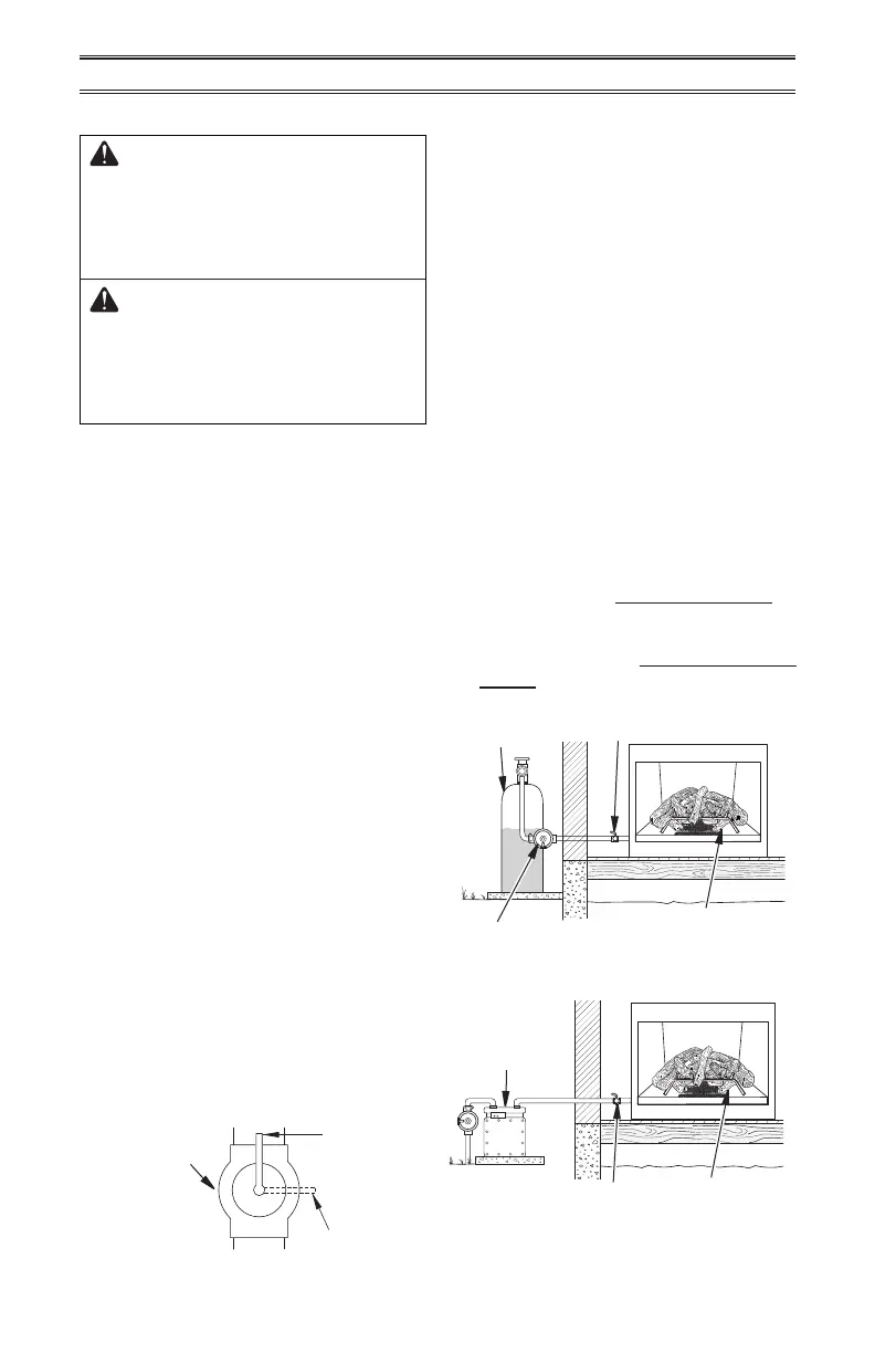
Figure 17 - Equipment Shuto Valve
CHECKING GAS CONNECTIONS
Open
Closed
Equipment
Shuto Valve
3. Check all joints from gas meter to equip-
ment shutoff valve for natural gas or
propanesupply to equipment shuto valve
for propane (see Figure 18 or 19). Apply
a noncorrosive leak detection uid to all
joints. Bubbles forming show a leak.
4. Correct all leaks at once.
PRESSURE TESTING HEATER GAS
CONNECTIONS
1. Open equipment shuto valve (see Fig-
ure 17).
2. Open main gas valve located on or near
gas meter for natural gas or open propane
supply tank valve.
3. Make sure control knob of heater is in the
OFF position.
4. Check all joints from equipment shuto
valve to control valve (see Figure 18 or 19).
Apply a noncorrosive leak detection uid
to all joints. Bubbles forming show a leak.
5. Correct all leaks at once.
6. Light heater (see Lighting Instructions on
page 19). Check all other internal joints
for leaks.
7. Turn o heater (see To Turn O Gas Ap-
pliance, page 20).
Control Valve
Location
Control Valve
Location
Equipment
Shuto Valve
Equipment Shuto Valve
External Regulator
Propane
Supply Tank
Figure 18 - Checking Gas Joints for
Propane Gas
Figure 19 - Checking Gas Joints for
Natural Gas
Gas Meter
WARNING: Test all gas piping
and connections, internal and
external to unit, for leaks after
installing or servicing. Correct
all leaks at once.
WARNING: Never use an open
ame to check for a leak. Apply a
noncorrosive leak detection uid
to all joints. If bubbles form, there
is a leak. Correct all leaks at once.
PRESSURE TESTING GAS SUPPLY
PIPING SYSTEM
Test Pressures In Excess Of 1/2 PSIG (3.5 kPa)
1. Disconnect heater with its appliance main
gas valve (control valve) and equipment
shuto valve from gas supply piping sys-
tem. Pressures in excess of 1/2 PSIG will
damage heater regulator.
2. Cap o open end of gas pipe where equip-
ment shuto valve was connected.
3. Pressurize supply piping system by either
opening propane supply tank valve for
propane gas or opening main gas valve
located on or near gas meter for natural
gas or using compressed air.
4. Check all joints of gas supply piping sys-
tem. Apply noncorrosive leak detection
uid to all joints. If bubbles form, there
may be a leak.
5. Correct all leaks at once.
6. Reconnect heater and equipment shuto
valve to gas supply. Check reconnected
ttings for leaks.
Test Pressures Equal To or Less Than
1/2 PSIG (3.5 kPa)
1. Close equipment shuto valve (see Fig-
ure 17).
2. Pressurize supply piping system by either
opening propane supply tank valve for
propane gas or opening main gas valve
located on or near gas meter for natural
gas or using compressed air.