v.080131 9
ENGLISH
5. Center the blade on the blade seat ange, making sure the blade ts at and the
raised hub of the ange goes through the hole in the blade. It is a good idea to
have the printed side of the blade facing up towards the operator as the white
printing makes the blade more visible while turning.
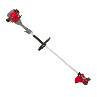
6. Place the blade retainer ange (S, g. 4) over the shaft with the raised centre
boss away from the blade and its 2 pins going down through the blade to
engage the matching dimples in the top surface of the blade seat ange (g. 9 &
10).
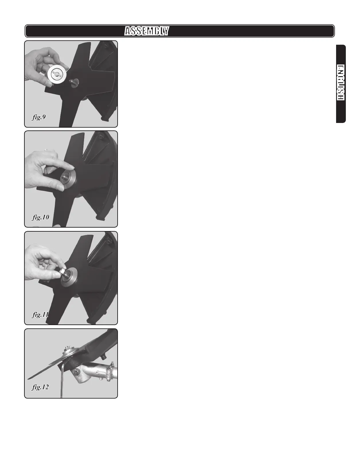
7. Place the M12 left-threaded hex blade nut (T, g.4) onto the gear head shaft
(g.11). Turn it counter-clockwise to tighten.
8. Align the hole in the blade seat ange with the hole in the gear head.
9. Insert the T25 torx driver wrench as a gear head locking tool through the slot in
the blade seat ange and gear head (g.12).
ASSEMBLY