12
R
L
R
L
R
L
PROEL suggested
equipment:
M-series mixer
dynamic microphone
PROEL suggested types:
DM580 - DM586 - DM226
DM220 - DM800
or
WM wireless mic
LEFT
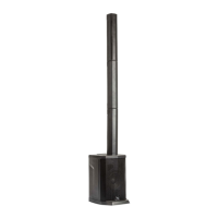
FLASH8A (sat)
RIGHT
FLASH8A (sat)
RIGHT
FLASH8A
LEFT
FLASH8A
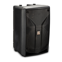
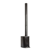
basic system
2x FLASH8A
FLASH8A
(mic in)
single voice system
FLASH8A
(line in)
single voice system
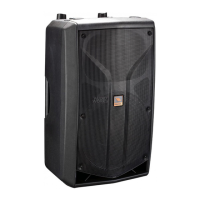
FLASH8A
(line in)
single voice system
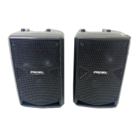
minimal
conference
system
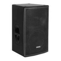
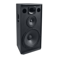
2x SW110A
+
2x FLASH8A
SW110A
(mono sub)
SW110A
(mono sub)
LEFT
FLASH8A (sat)
RIGHT
FLASH8A (sat)
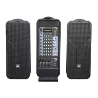
1x SW115A
+
2x FLASH8A
SW115A (stereo sub)
set this switch as stereo
FLASH 8A CONFIGURATIONS (FIG.3)
FLASH8A KONFIGURATIONSDIAGRAMME (ABB.3)
FLASH 8A CONFIGURAZIONI (FIG.3)
FLASH8A CONFIGURATIONS (FIG.3)
)3FLASH8A
FLASH8A CONFIGURACIONES (FIG.3)