1
1
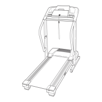
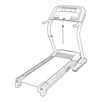
12. Lower the Uprights (31, 36). Be careful to not
damage the Left and Right Base Covers (90,
9
1).
S
ee the inset drawing. P
osition the Uprights
(31, 36) so that the treadmill Frame (74) is cen-
tered between the Uprights.
Firmly tighten the 3/8" x 2 1/4" Bolts (27) and the
3/8" x 3 1/2" Bolts (32) on each side of the
treadmill.
Do not overtighten the 3/8" x 3 1/2"
Bolts.
36
31, 36
32
74
74
31
View from Above
Side View
1
2
27
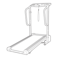
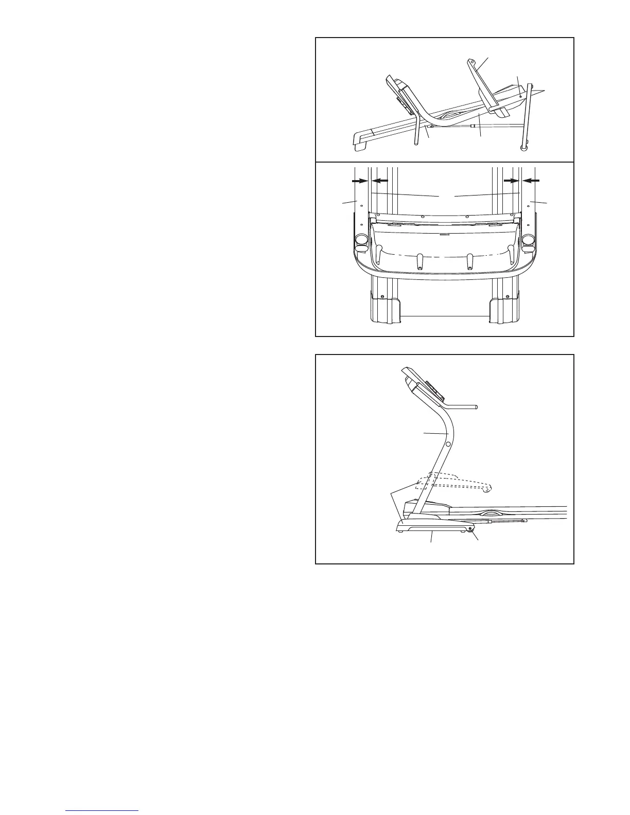
13. Raise the Uprights (31, 36).
Turn the Left and Right Base Covers (90, 91) to
the position shown. Slide the Base Covers down-
ward over the Base (48). If necessary, pull out on
the sides of the Base Covers to fit them over the
3/8" x 2 3/4" Bolts (14).
Lower the Uprights (31, 36).
90, 91
48
13
31, 36
14
90, 91