5
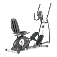
1. Hold the Stabilizer (68) against the saddle on the back
of the Base (1). Attach the Stabilizer with two M10 x
75mm Bolts (66) and two M10 Nylon Locknuts (54).
2. Slide the Rail Stabilizer (37) onto the Base (1), so the
ÒUÓ-channel on the stabilizer fits into the Base. Make
sure the Reed Switch Wire (48) is extending from
the hole that will be formed as the two parts slide
together. Make sure you donÕt damage the Reed
Switch Wire when the two parts meet.
Insert two M10 x 68mm Bolts (67) with two M10
Washers (71) up through the Base (1).
Insert two M10 x 68mm Bolts (67) with two M10
Washers (71) up through the Rail Stabilizer (37).
Note: It may be easier to insert the four Bolts by
tipping the unit on its side.
ASSEMBLY
Assembly requires two persons. Place all parts of the PROFORM
¨
REBEL in a cleared area and remove the
packing materials. Do not dispose of the packing materials until assembly is completed.
Assembly requires a phillips screwdriver , two adjustable wrenches and a
rubber mallet (none of these are included).
2
1
71
66
54
54
1
68
1
37
67
48
ÒUÓ-channel
3
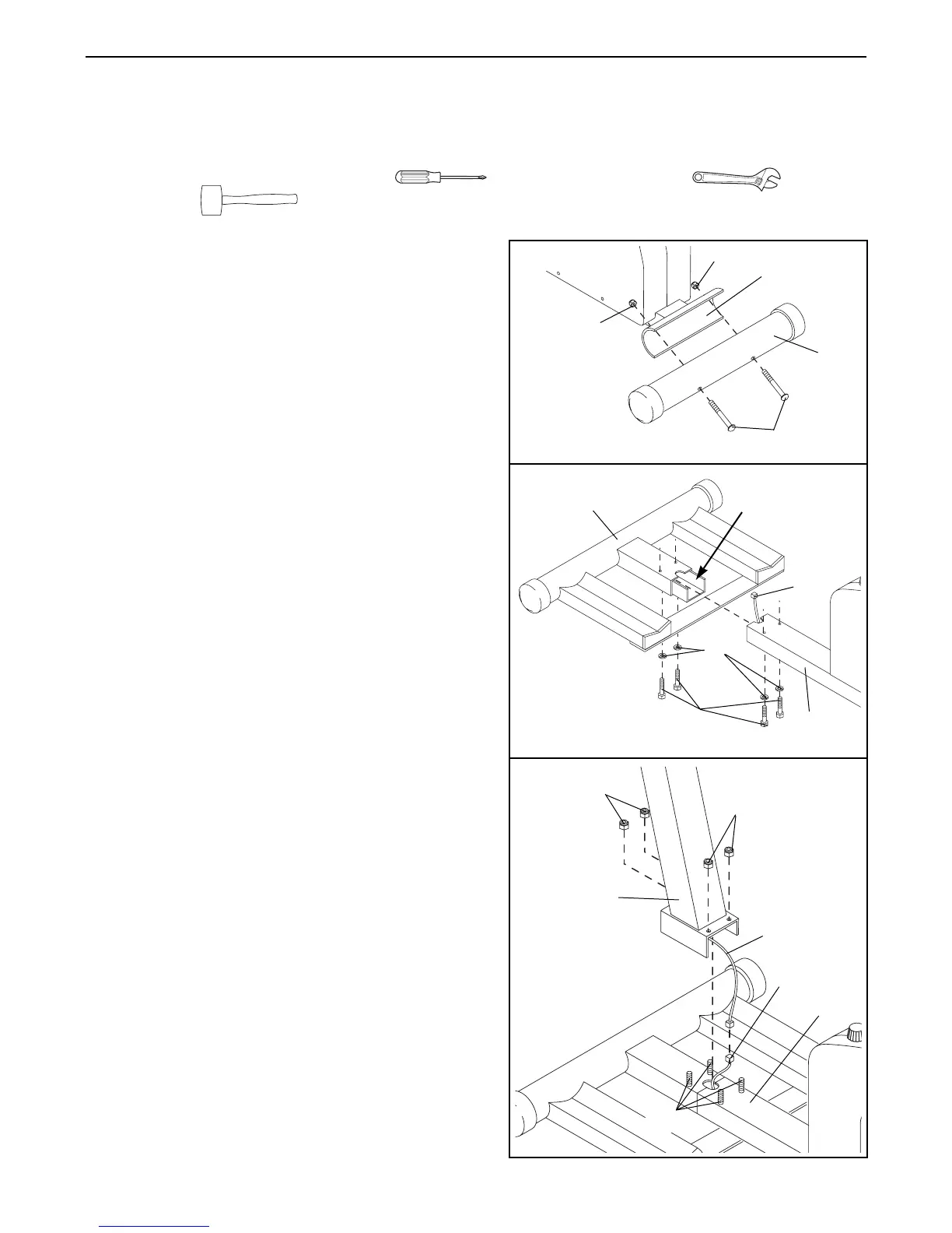
3. While one person holds the Upright (2), connect the
Extension Wire (49) coming from the Upright to the
Reed Switch Wire (48) extending from the Base (1).
Stuff any excess wire into the Upright or into the Base
(1).
Slide the Upright (2) onto the four M10 x 68mm Bolts
(67). Make sure you donÕt damage the wires as you
slide the Upright into place.
Hand tighten an M10 Nylon Locknut (54) onto each
M10 x 68mm Bolt (67). Tip the unit on its side and use
two wrenches to tighten the Locknuts fully.
54
2
48
49
1
54
67