5
68
1
3
1
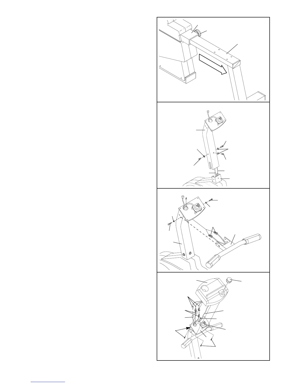
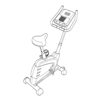
1. Loosen the Lock Knob (68) on the right side of the
Frame (1). Slide the Seat Frame (3) out until it
stops. Tighten the Lock Knob.
2. Attach the Upright (2) to the Frame (1) with three
M10 x 25mm Button Head Screws (25) and three
M10 Split Washers (26). Be careful not to pinch
the Reed Switch Wire (13) or the Resistance
Cable (10).
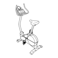
3. Route both Extension Wires (41) up through the
Upright (2) as shown.
Attach the Handlebar (4) to the Upright (2) with two
M6 x 25mm Hex Head Screws (14) and two M6 Split
Washers (67), but do not tighten the Screws yet.
Make sure that the Screws are threaded into the
indicated holes. Note: Two additional Screws will
be attached in step 5.
2
2
26
26
25
25
25
1
10
13
3
41
2
14
14
67
67
4
4. Connect the Reed Switch Wire (13) and the two
Extension Wires (41) to the corresponding wires on
the Console (8).
If your Console (8) has a ground wire, attach it to
the Upright (2) with an M4 x 16mm Screw (34).
Next, attach the Console (8) to the Upright (2) with
four #8 x 5/8Ó Screws (22).
Press the Resistance Knob (9) onto the Resistance
Control (10). Be sure that the mark on the Knob is
correctly aligned.
Console
Wires
Ground
Wire
10
8
9
13
34
2
41
22
22
4