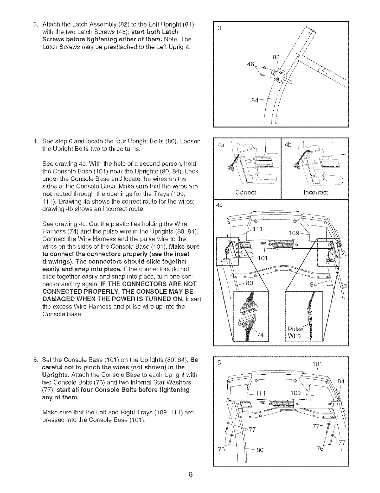
3, AttachtheLatchAssembHy(82)totheLeftUpright(84)
withthetwoLatchScrews(46);startbothLatch
Screwsbeforetighteningeither of them. Note: The
Latch Screws may be preattached to the Left Upright,
46
82
4, See step 6 and Hocatethe four Upright BoHts(86), Loosen
the Upright BoHtstwo to three turns,
See drawing 4c, With the heHpof a second person, hoHd
the ConsoHe Base (101) near the Uprights (80, 84), Look
under the ConsoHe Base and Hocatethe wires on the
sides of the ConsoHe Base, Make sure that the wires are
not routed through the openings for the Trays (109,
111), Drawing 4a shows the correct route for the wires;
drawing 4b shows an incorrect route,
See drawing 4c, Cut the pHasticties hoHding the Wire
Harness (74) and the puHsewire in the Uprights (80, 84),
Connect the Wire Harness and the puHsewire to the
wires on the sides of the ConsoHeBase (101 ), Make sure
to connect the connectors properly (see the inset
drawings}. The connectors should slide together
easity and snap into pJace. Hfthe connectors do not
slide together easily and snap into prince,turn one con-
nector and try again, IF THE CONNECTORS ARE NOT
CONNECTED PROPERLY, THE CONSOLE MAY BE
DAMAGED WHEN THE POWER msTURNED ON. Hnsert
the excess Wire Harness and puHsewire up into the
ConsoHe Base,
4a
4c
Correct
4b
Hncorrect
PuHse'_
Wire
5, Set the ConsoHe Base (101) on the Uprights (80, 84), Be
careful not to pinch the wires (not shown} in the
Uprights. Attach the ConsoHe Base to each Upright with
two ConsoHe BoHts(76) and two HnternaHStar Washers
(77); start aH four Consote Bolts before tightening
any of them.
Make sure that the Left and Right Trays (109, 111) are
pressed into the Console Base (101),
7_
101
76
6