EasyManuals Logo

Projecta IDC25 User Manual

Projecta IDC25
16 pages
To Next Page IconTo Next Page
To Previous Page IconTo Previous Page
Page #10 background imageLoading...
Page #10 background image
10
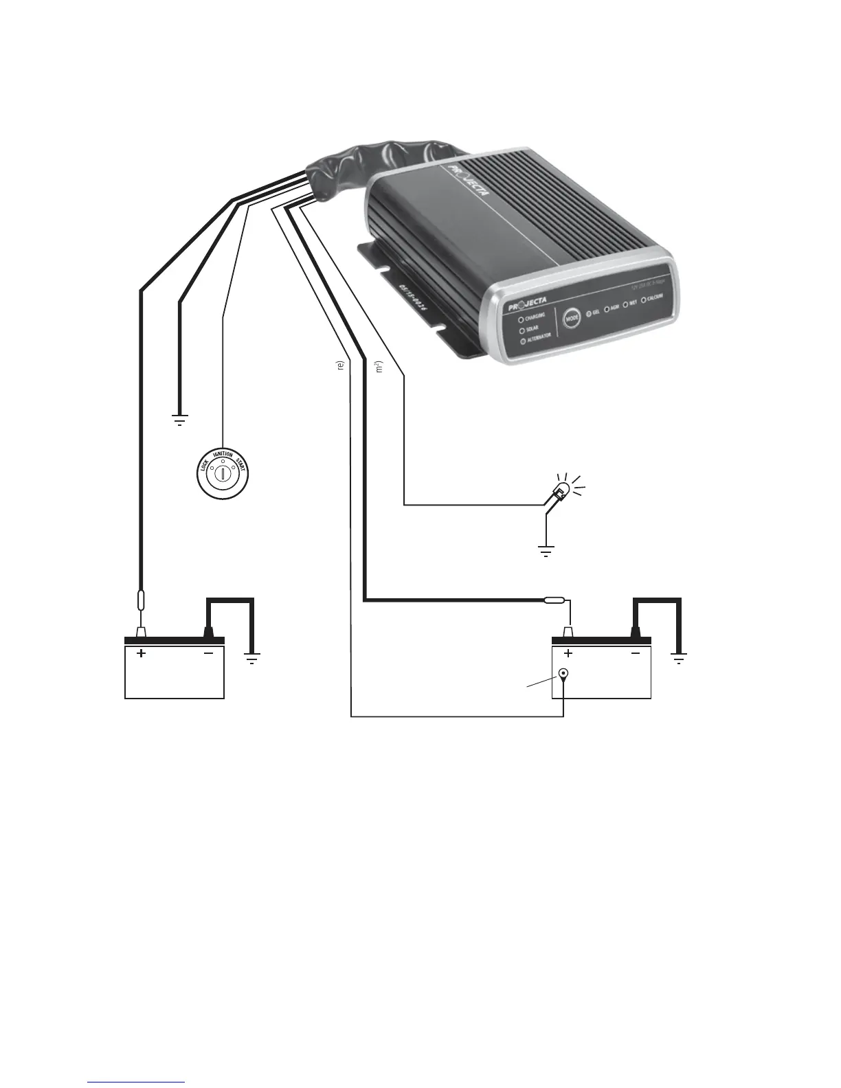
2. Alternator/Starter Battery Input Only
For vehicles fitted with
a Smart Alternator only
LED Panel
Mount Indicator
Earth/Chassis
Alternator/Starter Battery – Red (8mm
2
)
Ground/Chassis – Black (8mm
2
)
Ignition override – Blue (1.5mm
2
)
External LED – Pink (1.5mm
2
)
Output/Auxiliary Battery – Grey (8mm
2
)
Temperature Sensing – Black (twin core)
Temp Sensor mount
to battery casing
connects to ignition feed if smart alt.
Earth/ChassisGround/Chassis
Fuse
Fuse
Battery 2
(Aux Battery)
Battery 1
(Starter Battery)
* Optional
*
*
*

Questions and Answers:

Question and Answer IconNeed help?

Do you have a question about the Projecta IDC25 and is the answer not in the manual?

Projecta IDC25 Specifications

General IconGeneral
Input Voltage9-32V DC
Output Voltage12V DC
Output Current25A
Battery ChemistryAGM, Gel, Calcium
ApprovalsE-Mark
Protection FeaturesOver Temperature, Reverse Polarity

Related product manuals