15
SMARTbAT
Example 6 DMX channels conguration
Number of
DMX channels
Start address
(example)
DMX Address
occupied
Next possible start
address for unit No. 1
Next possible start
address for unit No. 2
Next possible start
address for unit No. 3
4 33 33-36 37 41 45
6 33 33-38 39 45 51
10 33 33-42 43 53 63
. . . . . . . . . . . .
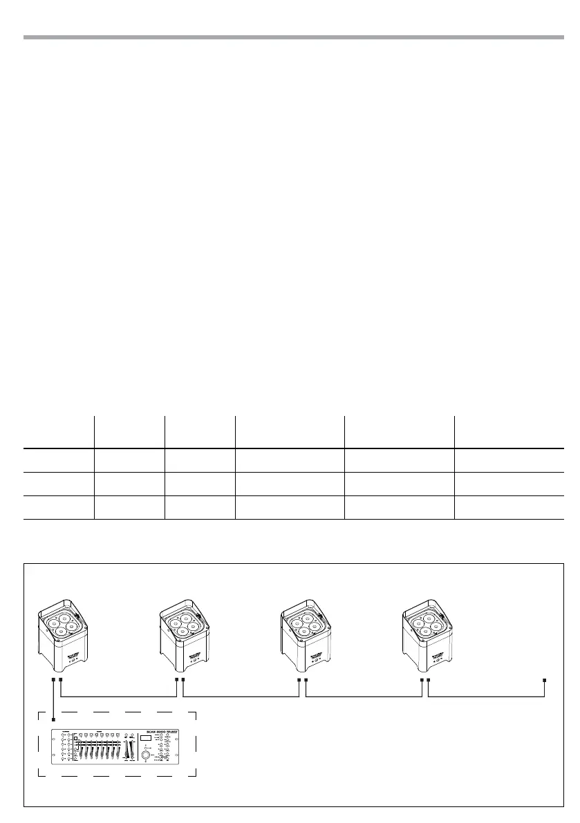
DMX512 Controller
Fig.10
DMX Address: 33 DMX Address: 51DMX Address: 39 DMX Address: 45
3.17 LINKING
1. Connect the DMX OUT of the master unit via 3-pole XLR cable to the DMX IN of the rst slave unit.
2. Connect the DMX OUT of the rst slave unit to the DMX IN of the second slave unit, etc. until all units
are connected in a chain.
3.18 DMX MODE
• Press the button MENU so many times until shows, [CH4], [CH6] or [CH10] and press the button ENTER to
conrm.
• Press the button UP/DOWN to select the desired DMX address [d001 - d512]. Press and hold to scroll
quickly. Press ENTER button to store.
The tables on page 17 indicate the operating mode and DMX value. The SMARTBAT is equipped with 3
pole XLR connections.
3.19 DMX ADDRESSING
To able to operate the SMARTBAT with a light controller, adjust the DMX start address for the rst a DMX
channel. If e. g. address 33 on the controller is provided for controlling the function of the rst DMX chan-
nel, adjust the start address 33 on the SMARTBAT.
The other functions of the light eect panel are then automatically assigned to the following addresses. At
the next page an example with the start address 33 is shown below: