5
WiFiBoX
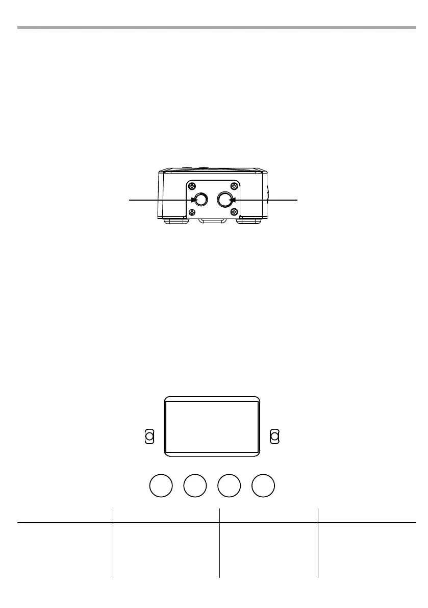
Fig.2
MENU UP DOWN ENTER
- 2 - INSTALLATION
2.1 MOUNTING
WIFIBOX may be set up on a solid and even surface. The unit can also be mounted upside down to a cross
arm. For xing, stable mounting clips are required. The mounting place must be of sucient stability and
be able to support a weight of 10 times of the unit’s weight. When carrying out any installation, always
comply scrupulously with all the regulations (particularly regarding safety) currently in force in the coun-
try in which the xture’s being used. IMPORTANT - Always additionally secure the product with the safety
rope from falling down. For this purpose, fasten the safety rope at a suitable position so that the maximum
fall of the product will be 20 cm.
THREADED HOLES
- 3 - FUNCTIONS AND SETTINGS
3.1 OPERATION
For to operate on the WIFIBOX, connect the supplied main cable to a socket (100-240V~/50-60Hz). Then
the unit is ready for operation and can be operated via a DMX controller. To switch o, disconnect the
mains plug from the socket. For a more convenient operation it is recommended to connect the unit to a
socket which can be switched on and o via a light switch.
3.2 BASIC SETUP
The WIFIBOX has a LCD display and 4 buttons for access to the functions of the control panel (Fig. 3).
MENU UP DOWN ENTER
Used to access the menu or
to return a previous menu
option
Button to select the values
in ascending order of the
function
Button to select the values
in descending order of the
function
Used to select and store the
current menu or conrm the
current function value or
option within a menu
Fig.3 - Functions of the buttons
THREADED HOLES