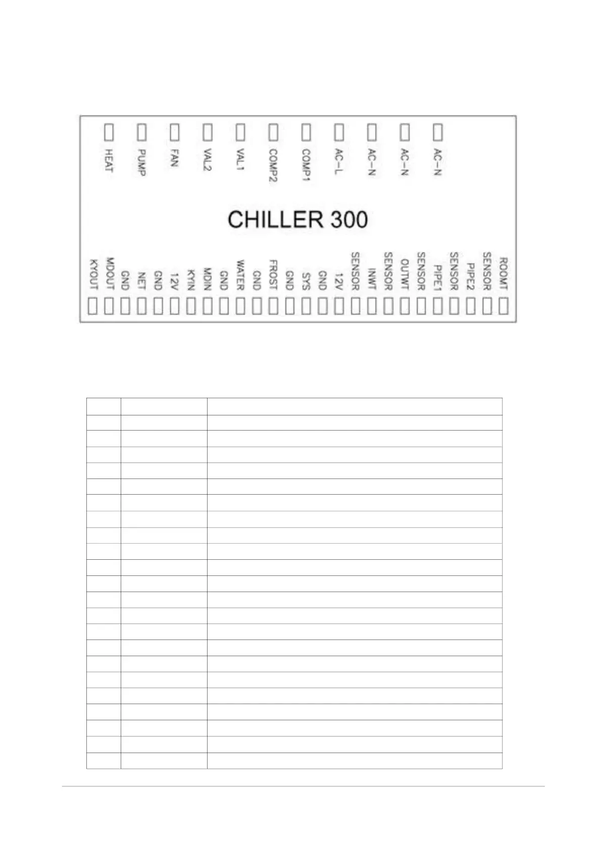
6. Connection Table
Connection legend:
No. Symbol Meaning
1 HEAT Underpan heat cable output: 220-240 VA
2 PUMP Water pump: 220-240 VA
3 FAN Fan motor: 220-240 VA
4 VAL2 Solenoid valve: 220-240 VA
5 VAL1 Four-way valve of system 1 : 220-240 VA
6 COMP2 Compressor of system 1 : 220-240 VA
7 COM 1 Compressor of system 2 : 220-240 VA
8 AC-L Live wire
9 AC-N Neutral wire
10 KYOUT GND ON/OFF switch (output, not used)
11 MDOUT GND Mode output (not used)
12 NET GND 12 V Wire controller
13 KYIN ON/OFF switch (input, not used)
14 MDIN Mode input (not used)
15 WATER GND Flow switch (input, normally closed)
16 FROST GND Defrost signal (not used)
17 SYS GND 12V System protection (input, normally closed)
18 ROOMT Ambient temperature (input)
19 PIPE2 Temp. of coil 2 (input, not used in system )
20 PIPE1 Temp. of coil 1 (input)
21 OUTWT Temperature of out-going water (input)
22 INTWT Temperature of in-going water (input)
P
1
21
10 11 11 12 12 12 13 14 14 15 15 16 16 17 17 17 22 21 20 19 18
12345678999