))5B95C9B5<1B=?>DB?<&1>5<
*I@931<&1>5<-9B5(?ED9>75D19<
)
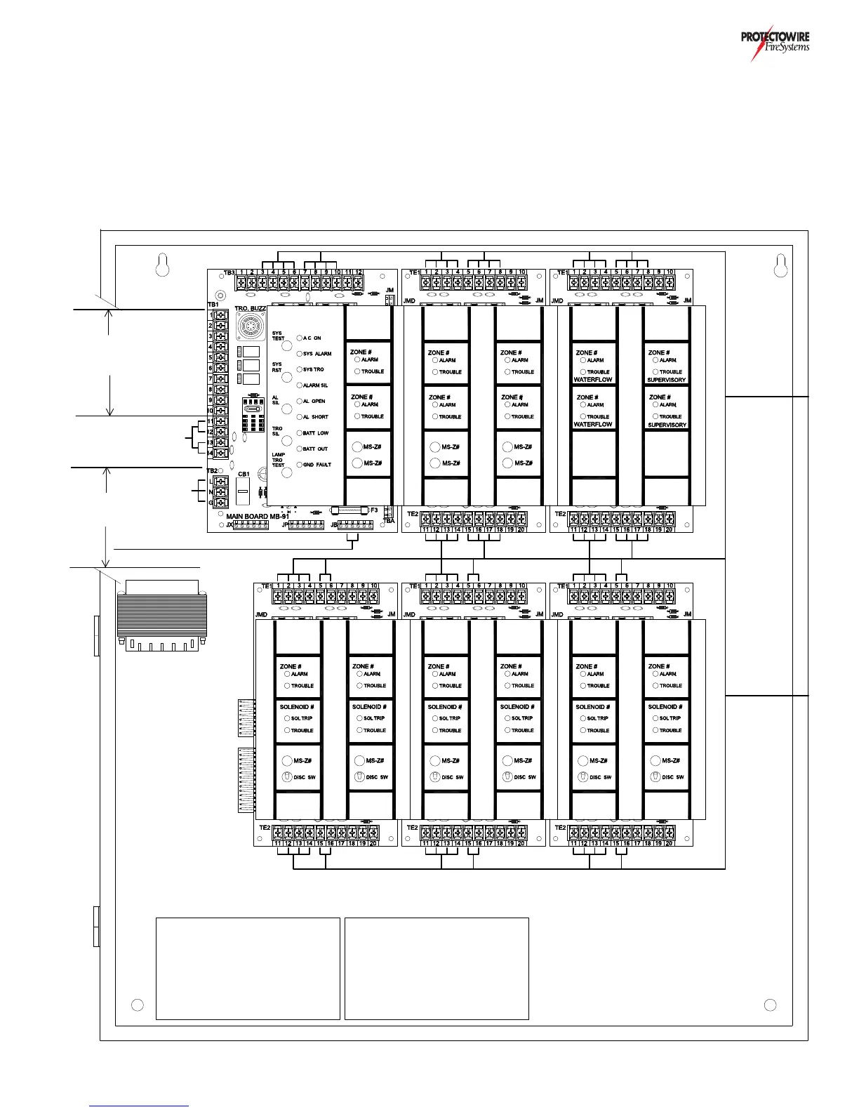
When bringing field wires to and from the control panel you must maintain segregation between Power Limited and
Non-Power Limited wiring. Use the illustration below as a guideline for routing wire within the system enclosure. Also
reference the field wiring sections of this manual to determine which field connections are Power Limited and which
are Non-Power Limited.
ALARM
NOTIFICATION
APPLIANCE
CIRCUITS
SYSTEM
AC POWER
POWER
LIMITED
DETECTION
CIRCUITS
SYSTEM BATTERY POWER
IF IN SEPARATE ENCLOSURE
TRANSFORMER
POWER
LIMITED
DETECTION
CIRCUITS
BATTERY 12VDC
IF IN SAME
ENCLOSURE
BATTERY 12VDC
IF IN SAME
ENCLOSURE
NOTE ALL POWER LIMITED WIRING
MUST BE SEGREGATED FROM POWER
LIMITED WIRING WITH A MINIMUM OF
TWO CABLE ENTRY OPENINGS AND
1/4" SPACING BETWEEN THE TWO
CONDUCTOR TYPES
NON-POWER
LIMITED
CIRCUITS
POWER
LIMITED
CIRCUITS
* POWER
LIMITED
CIRCUITS
DRY
CONTACTS
* COMMON ALARM, COMMON TROUBLE &
COMMON SUPERVISORY
DRY CONTACTS FOR CONNECTION
TO POWER LIMITED CIRCUITS ONLY
~ 11 ~