SUPERVISORY
E
or
240VAC 50/60Hz
0.85 AMP. MAX.
N.O. / N.C.
COM.
N.O. / N.C.
COM.
N.O. / N.C.
COM.
N.O.
COM.
N.C.
*SILENCEABLE
NON-SILENCEABLE
SILENCEABLE
SILENCEABLE
~ 21 ~
#19>?1B4##95<4-9B9>7
)D1>41B4<1CC
<1B=$?D96931D9?>
@@<91>359B3E9DC
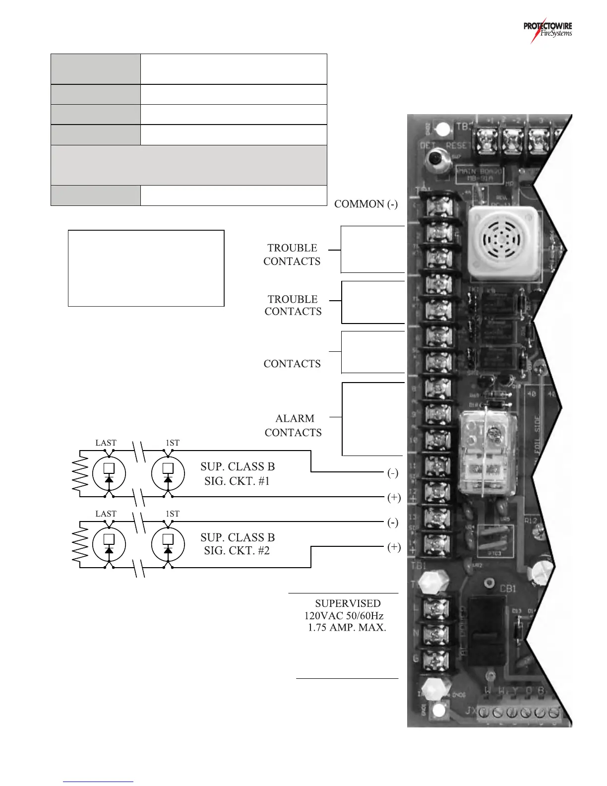
Note: Polarity of Notification Appliance
Circuits shown in Alarm Condition.
?B<1CC1<1B=>?D96931D9?>
1@@<91>3539B3E9DCB565B5>35
%@D9?>L*M@175?6D89C=1>E1<
#19>?1B4
##
*B1>C6?B=5B?>>53D9?>C
Common Trouble
Contacts
1 amp @ 24 VDC, Resistive load 2 sets available.
See Option “S” page for silencable & non-
silenceable operation
Common Supervisory
Contacts
1 amp @ 24 VDC, Resistive load 1 set available
(non-silenceable)
Common Alarm
Contacts
3 amps @ 30 VDC, Resistive load 1 set available
(silenceable)
Notification Appliance
Circuits
2 amps per circuit 3 amps maximum combined @
19 - 32.6V FWR
Note: Notification Appliance Circuits current rating may be reduced
Depending on each systems current requirements. Reference the
Installation Wiring Diagram (IWD) for individual systems actual ratings.
Reference Data Sheet DS-9066 for more information
AC Power
Connections
120 VAC 50/60 Hz, 175 Volt Amps Standard.
240 VAC 50/60 Hz, 175 Volt Amps (available)
ELR-4.7K
1/2 W
ELR-4.7K
1/2 W
REFERENCE FW-1408 LOCATED
ON INSIDE OF CABINET DOOR
FOR TROUBLE/SUPERVISORY
CONTACT POSITIONS &
JUMPER SETTINGS
*NON-SILENCEABLE WITH B2
JUMPER ON CC-91A IN THE 1-2
(NON-SIL) POSITION