))5B95C9B55D53D9?>
5<E75&B513D9?>?>DB?<&1>5<>6?B=1D9?>1>4)@5396931D9?>C
The FS2000 Series of multiple zone fire protection panels is the latest in fire protection from The Protectowire Company, Inc. The
standard model provides, as a minimum, 2 (Class A or B) initiating device circuits and the following standard features:
- Expandable (in multiples of two zones) - Ground Fault Detection (not applicable to all systems)
- Two Supervised Notification
Appliance Circuits - Alarm Lock-in until Reset
- On Board Audible Indicator Silencing - On Board System Reset Button
- Lamp and System Trouble Circuit Test - Dry Alarm and Trouble Contacts
- Initiating Device (Detection) Circuit -IDC- ALARM Test
- Monitors up to 5,000 ft. (1,524 meters) of PROTECTOWIRE Linear Heat Detector Cable per circuit
- Any combination of normally open contact devices
- Accommodates up to (30) NS-series #SLR-24, #SIJ-24, #SLR-24H, Detector Identifier - HD-3
Smoke Detectors (per circuit).
- Battery Monitoring, Low or Out of operating specs. (or disconnected)
)ICD5=)@5396931D9?>C
$?D96931D9?>@@<91>359B3E9DC
Note: Circuits do NOT generate a temporal pattern signal. Appliances that can generate a temporal pattern must be employed
when a temporal pattern is required. Reference DS-9066 in this manual for compatible devices.
~ 4~
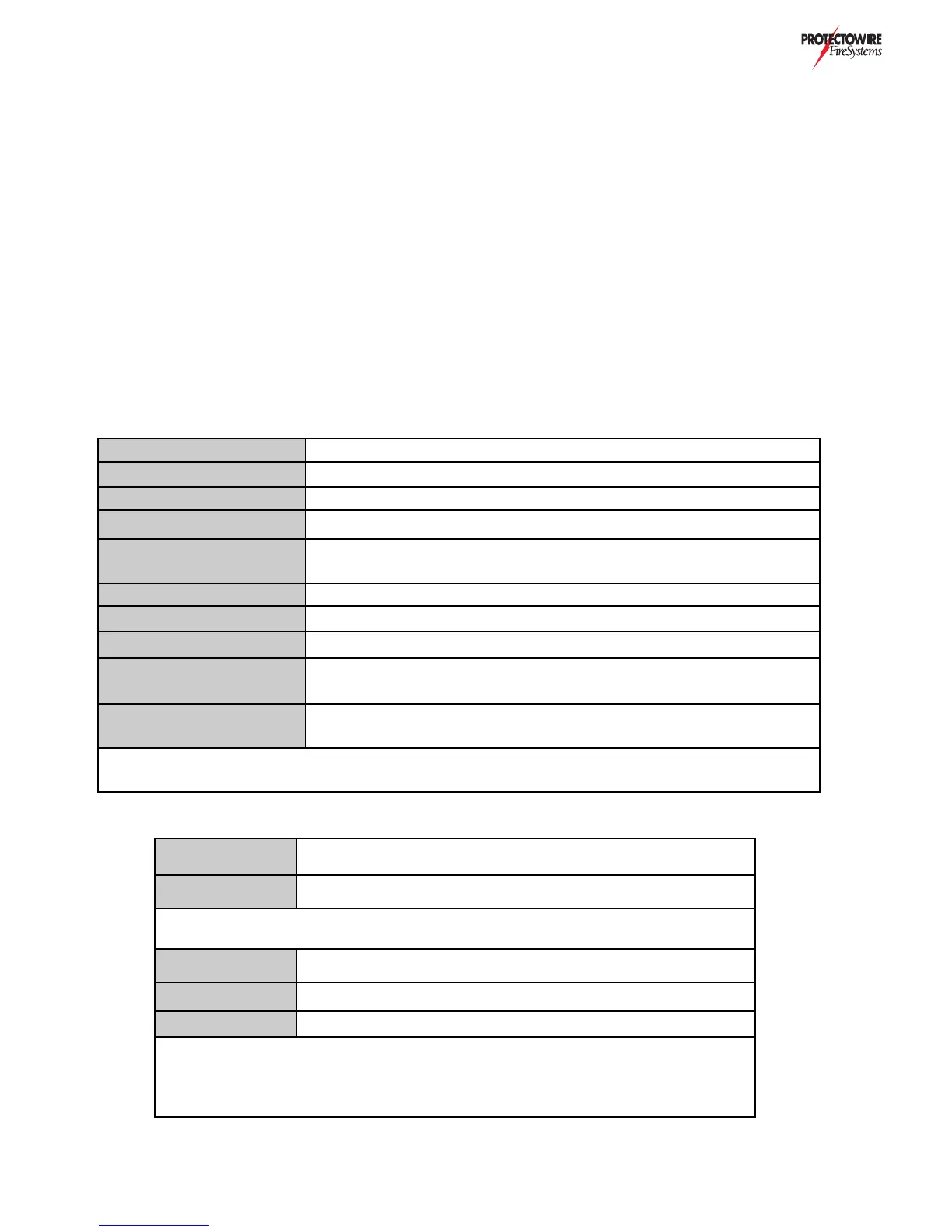
&B9=1BI&?G5B
120VAC 50/60Hz 1.75 amp maximum ** see below
)E@@?BD54)D1>42I1DD5B95C
24VDC 4.5AH minimum to 60AH maximum * see below
1DD5BI81B75B
27VDC 1.25 Fast charge, 27.6mA Max trickle charge, 12mA (typical)
&B9=1BI)ICD5=&?G5B
24V FWR by T1, 175VA typical. Greater VA rating as required by system
)ICD5=(57E<1D54&?G5B
MB and EB type boards provide 12 & 24VDC regulation. RS type boards
provide24VDC regulation only
?==?><1B=?>D13DC
3 amps @ 30VDC, resistive load, silenceable
?==?>*B?E2<5?>D13DC
1 amp @ 24VDC, resistive load, factory preset as non-silenceable
?==?>)E@5BF9C?BI?>D13DC
1 amp @ 24VDC, resistive load, programable
?EBG9B545D53D?B@?G5B
24VDC @ 200mA Max. used for Special Application
(non-supervised, for supervision use PSR-2040)
>F9B?>=5>D1<?@5B1D9>7
3?>49D9?>C
Ambient temperatures: 32 - 120 degree F (0 - 49 degrees C)
Humidity: Max. 95% relative non-condensing
*Battery requirements calculated per individual system demands. (See battery selection data)
**240VAC 50/60 Hz 0.85amp maximum also available. Check installation wiring diagram (IWD).
,?<D175
24 V Full wave rectified (FWR) with battery standby.
EBB5>D
Two amps per circuit three amps maximum combined
Maximum two conductor copper feed cable resistance may not exceed 1 ohm (see below
1.4 Volts Maximum Line Loss
-
Maximum of 500’ (feet)
-
Maximum of 300’ (feet)
N-
Maximum of 200’ (feet)
Note: Notification Appliance Circuits current rating may be reduced depending on
each systems current requirements. Reference the installation wiring diagram (IWD)
for individual systems actual ratings. Reference DS-9066 for more information