~ 27 ~
System control switches, lamp
indicators and signal monitoring
are managed with this module.
Plug-in design allows for quick
replacement during field repair.
Used in conjunction with the
Main Board (MB-91A).
Standard control card module is
designated as CC-91ANT. This
card eliminates the possibility of
accidental releasing by remov-
ing the “SYS. TEST” button.
?>DB?<1B4#?4E<5
9C@<1I
&1>5<
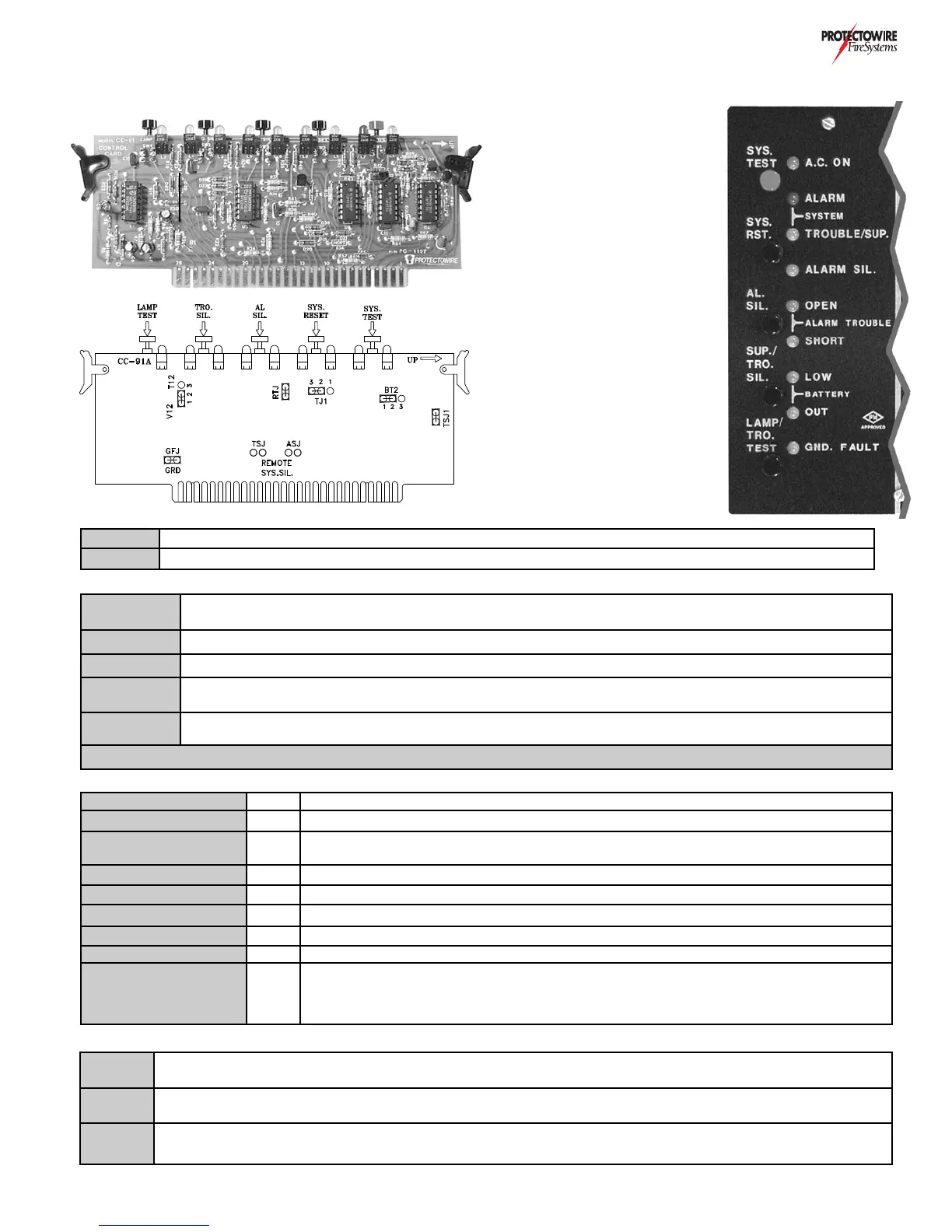
The Control Card CC-91A provides system controls and indicator for the FS2000 Series system. This card
plugs into the Main Board MB-91A/M printed circuit board left side card slot.
?>DB?<)G9D385C
>4931D?BC
&&""%(+"")*)/)*#)%$"/
N,1B91D9?>C
CC-91A Control card module with “SYS.TEST” switch. This card must be specifically requested at time of purchase
CC-91ANT No test switch control card module: For use with releasing system where test feature is not desired (Standard)
SYS. TEST
System test button: Press and hold for a minimum of 3 seconds. Simulates ALARM condition in all detection
and supervisory zones. (Only available when specified on systems without solenoid release) *See warning
SYS. RESET System Reset button: Press to reset system from ALARM condition.
AL. SIL Alarm Silence button: Press to silence Alarm Notification Appliance devices activated by ALARM condition
SUP./TRO.
SIL.
Trouble/Supervisory alarm silence button: Press to silence activated common trouble signal (pulsing buzzer)
or supervisory alarm signal (steady buzzer)
LAMP/TRO.
TEST
Lamp and trouble test button: Press to test lamp indicators and system trouble signaling
*Warning: Disconnect all releasing devices and/or equipment shutdown prior to testing system. See Testing & Maintenance section
AC ON Green AC Power indicator: ON when panel AC voltage is present
SYSTEM ALARM Red System alarm indicator: Activated when any zone ALARM occurs
SYSTEM TROUBLE/
SUP.
Yellow
System trouble indicator: Flashing when system TROUBLE exists. Steady when system
SUPERVISORY ALARM condition exists
ALARM SIL. Yellow Alarm silenced indicator: Flashing when Alarm Notification A2728ppliance circuits are silenced.
ALARM OPEN Yellow Alarm notification appliance circuit OPEN indicator: ON when OPEN exists in circuit.
ALARM SHORT Yellow Alarm notification appliance circuit SHORT indicator: ON when SHORT exists in circuit.
BATTERY LOW Yellow Battery low indicator: ON when battery voltage level is below allowed minimum.
BATTERY OUT Yellow Battery out indicator: ON when battery disconnect or above normal operating voltage below
GND. FAULT Yellow
System ground fault indicator: ON when undesirable positive or negative current leakage occurs
to grd from DC power supply of system. Not available with intrinsic safety barriers (Option H)
E=@5B)5DD9>7C
GFJ
Placed across GFH terminals 1 & 2 to enable ground fault detection. Jumper removed ONLY when diode shunt type
intrinsic safety barriers are employed
ASJ & TSJ
Jumpers are installed when option Z is part of panel design. These jumpers allow the Alarm (ASJ) and Trouble (TSJ)
signals to be silenced.
BT2J
Allows the common trouble output drive to be either Silenceable or Non-Silenceable. To conserve battery power
this jumper is typically installed in the Non-Silenceable position.