~ 56 ~
))5B95C9B5<1B=?>DB?<&1>5<>CDBE3D9?>C
(5<51C5)G)E@5BF9C?BI
?1B49C@<1I
#19>?1B49C@<1I
H@1>45B?1B49C@<1I
DS-9039C
)ICD5=?>DB?<)G9D385C
"%")(,(&()$**,
)ICD5=>4931D?BC
*)$)*(+*%$)#+)*#%+$*-*$*)/)*#$"%)+(%((#$#%+$*
$**%*$"%)+(
$1=5
44B5CC
&8?>5
)/)*)*
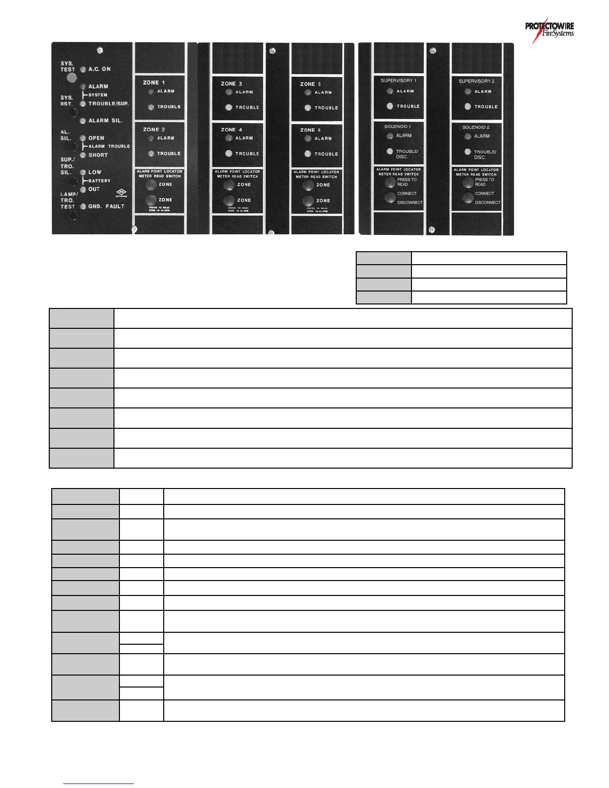
System test button: Press and hold for a minimum of 3 seconds. This simulates an ALARM condition in all
detection and supervisory zones. This test feature is applicable to systems without solenoid releasing (Option G) only.
)/)()* System reset button: Press to reset system from ALARM condition.
")" Alarm silence button: Press to silence notification appliances activated by ALARM condition.
*(%)"
Trouble/Supervisory alarm silence button: Press to silence activated common trouble signal (pulsing buzzer) or
supervisory alarm signal (steady buzzer).
"#&*(%
*)*
Lamp and trouble test button: Press to test indicator lamps and system trouble signaling.
#)0
Meter read switches: Press and hold to read distance (ft/m) to alarm actuation point of Protectowire zone in alarm.
See Option A - Protectowire alarm point location meter.
+*%)*%&
#$+"
Scanner mode switch: Slide switch to appropriate position for automatic scanning, stop at an individual zone or
to manually step to a particular zone.
)%"))- Solenoid disconnect switch: toggle to down position to inhibit solenoid activation on receipt of an alarm signal.
%$ Green A.C. Power indicator: Panel AC voltage present.
)/)"(# Red System alarm indicator: Activated when any zone ALARM occurs.
)/)*(%
)+&)
Yellow
System trouble indicator: Flashing when system TROUBLE exists. Steady when system
SUPERVISORY ALARM condition exists.
")" Yellow Alarm silenced indicator: Flashing when alarm notification appliance circuits are silenced.
"%&$ Yellow Alarm notification appliance circuit open indicator: On when open exists in circuit.
")%(* Yellow Alarm notification appliance circuit short indicator: On when short exists across circuit.
**"%- Yellow Battery low indicator: On when batteries voltage level is below allowed minimum.
**%+* Yellow Battery out indicator: On when batteries are disconnected or above normal operating voltage.
$+"* Yellow
System ground fault indicator: On when undesirable positive or negative current leakage occurs to
ground from DC power supply of system. Not available with Option H
0%$
"(#
Red
Zone alarm indicator: On in respect to each zones alarm condition.
Supervisory zone alarm indicator: On in respect to each supervisory zone alarm condition.
Yellow
0%$
*(%+"
Yellow Zone trouble indicator: On in respect to each zones trouble condition.
%&$)
)%(*
Yellow
Solenoid Open/Disconnected indicator: On in respect to solenoid circuit being open or disconnected.
Solenoid short indicator: On in respect to solenoid circuit being shorted.
Yellow
+00( TBZ
Trouble buzzer: Pulsing audible indication for all trouble conditions. Steady audible indication for all
supervisory alarm conditions.