18
1
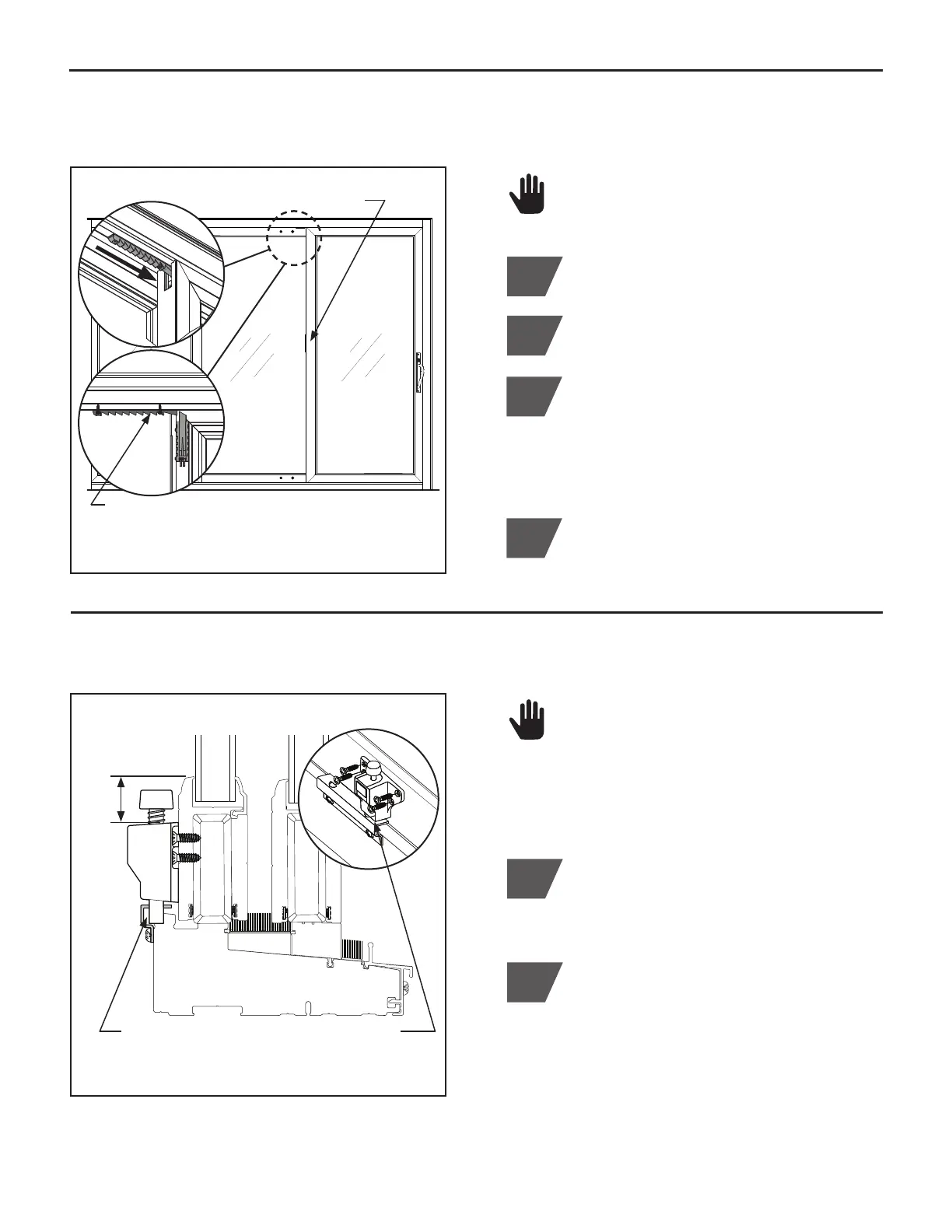
Close active sash and lock handle.
2
Flip AccuVent lever down into locked
position. (Figure L.1)
3
Locate the AccuVent bolt plate (AccuVent
Bolt Plate Kit) on the active sash header
track. Slide plate into the stile opening of the
active sash, next to the AccuVent bolt, as
shown in Figure L.1. Provide a
1
⁄8" clearance
between bolt plate and bolt. (Figure L.1)
4
Pre-drill a
3
⁄32" or
7
⁄64" hole and install (2)
#8 x 1" screws (AccuVent Bolt Plate Kit).
DO NOT over-tighten screws. (Figure L.1)
L. INSTALL ACCUVENT
™
VENTING SYSTEM BOLT PLATE
(Figure L.1)
Interior View
Flip AccuVent lever down
Locate AccuVent bolt plate, slide plate into
opening of active sash, leave
1
⁄8" clearance,
install with (2) #8 x 1" screws
AccuVent is a standard feature on all
Endure
™
and an optional feature on all
Aspect
™
.
M. INSTALL FOOT LOCK
Foot lock is a standard feature on all
Aspect
™
and an optional feature on all
Endure
™
.
Foot lock keeper is factory mounted.
1
Close active sash and lock handle.
Align foot lock (Pack #6) over the first hole
of keeper, closest to the latch side. Locate
and install foot lock body a minimum of
15
⁄16"
below top of sash rail, as shown. Check to
be sure bolt will engage keeper. Secure to
sash using (4) #8 x
3
⁄4" Phillips oval head
screws (Pack #6). (Figure M.1)
2
(Figure M.1)
Foot Lock Section View
15
⁄16"
Latch
Side
Align foot lock over first hole of keeper,
locate a minimum of
15
⁄16" below top of sash rail,
secure using (4) #8 x
3
⁄4" screws
Top of sash rail