- 10 -
2. Column with flange
3. Fastening block for lathe, including mounting parts
4
. ER 16 collets Ø 6, 8 and 10 mm
5
. Milling table with T-slots for mounting on the PD 230/E,
PD 250/E or PD 400, including mounting parts.
6. Operating tools
7
. Operating and safety instructions
2.3 FF 250/BL:
1
. Milling head, complete
2. Column with flange
3. ER 16 collets Ø 6, 8 and 10 mm
4. Compound table KT 230
5. Operating tools
6. Operating and safety instructions
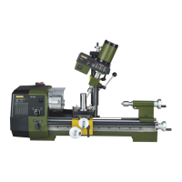
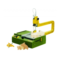
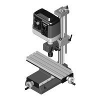
2.4 General view of milling cutter PF 250/BL
(Fig. 1)
1. Milling head
2. Handwheel for height adjustment
3. Clamping screw for height adjustment
4. Scale for angle adjustment
5. Drilling lever
6. Column with flange
7. Fastening block for lathe (only for PD 250/BL)
8. Milling table for lathe (only for PD 250/BL)
9. Sleeve nut for collet
10. Spindle
11. Clamping screw for quill
12. Scale ring with scale for depth adjustment
13. Quill
14. Speed table
15. On/Off switch
16. Rotational speed adjusting knob
17. Speed indicator
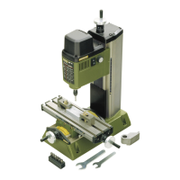
2.5 General view of compound table KT 230
(Fig. 2)
1. Handwheel for X direction
2. Scale ring
3. Work table
4. Hole for table attachment
5. Base
6. Handwheel for Y direction
7. Support
8. Clamping screw
9. Scale
10. Screw for column clamp
11. T-slots
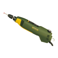
2.6 Technical data of milling cutter FF/PF 250/BL
(Fig. 3)
Voltage: 230 Volt, 50/60 Hz
Output: 250 watt
Brushless DC motor with direct drive of spindle
Rotational speed: infinitely variable from
400-6000 rpm
Sleeve stroke: 30 mm
Vertical setting range: 200 mm
Dimensions: See Fig. 3
M
ass: approx. 5 kg (without
c
ompound table)
Noise generation: less than 70 dB (A)
Vibration: less than 2.5 m/s2
2.7 Technical data of the compound table KT 230
(Fig. 4):
Work area: 270 mm x 80 mm
Adjustment travel in X direction: 170 mm
A
djustment travel in Y direction: 60 mm
W
eight: 9.5 kg
Dimensions of T-grooves: refer to Fig. 4
Groove spacing: 25 mm
Feed per rotation: 1.5 mm
Feed per graduation line: 0.05 mm
2.8 Noise/vibration information
The information on vibration and noise emission has been
determined in compliance with the prescribed standardised
and normative measuring methods and can be used to com-
pare electrical devices and tools with each other.
These values also allow a preliminary evaluation of the loads
caused by vibration and noise emissions.
Warning!
Depending on the operating conditions, the emissions that
actually occur may deviate from the values given above!
This applies in particular depending on the workpiece to be
machined and the insert tool (especially its wear condition).
Unsuitable workpieces or materials, poorly maintained tools,
too high a feed rate or unsuitable insert tools can significantly
increase the vibration load and noise generation.
To more accurately estimate the actual vibration and noise
load, also take the times into consideration where the device
is switched off, or is running but is not actually in use. This
can clearly reduce the vibration and noise load across the
entire work period.
Warning:
• Ensure regular and proper maintenance of your tool
• Stop operation of the tool immediately if excessive
vibration occurs!
• Unsuitable bits and cutters can cause excessive vibration
and noises. Only use suitable bits and cutters!
• Take breaks if necessary when working with the device!
3 Mounting the milling cutter
3.1 Mounting the milling cutter on a lathe (Fig. 5,
Fig. 6 and Fig. 7a)
1 Mounting lathe on a firm base.
2 Attach the mounting block 1 (Fig. 5) to the lathe 4 using
screws 2 and 3 (Do not tighten screws yet!)
3 Insert in pillar and tighten screws 2 and 3 to clamp pillar.
4 Attach the milling table 3 (Fig. 6) to the lathe support using
screws 2 and square nuts 1.
 Loading...