VP Keypad Access Device
12
114A3868.E rev. 7-2017
8
Ensure that both wires are seated all the way inside the slot.
Use a flathead precision screwdriver to tighten down the
terminal screw.
9
Verify that the terminal slot has tightened down on the copper
wire and not on the rubber insulation. There should be no
copper wire showing outside of the terminal slot. Gently tug
the wires to verify that they are tightly held inside the terminal
slot.
10
Insert both black wires into terminal slot 3 on P1. Ensure
that both wires are seated all the way inside the slot.
Repeat this process with each of the remaining wire
connections, placing them as shown in “Drawing 8: Terminal
block P1 wiring” on page 11.
11
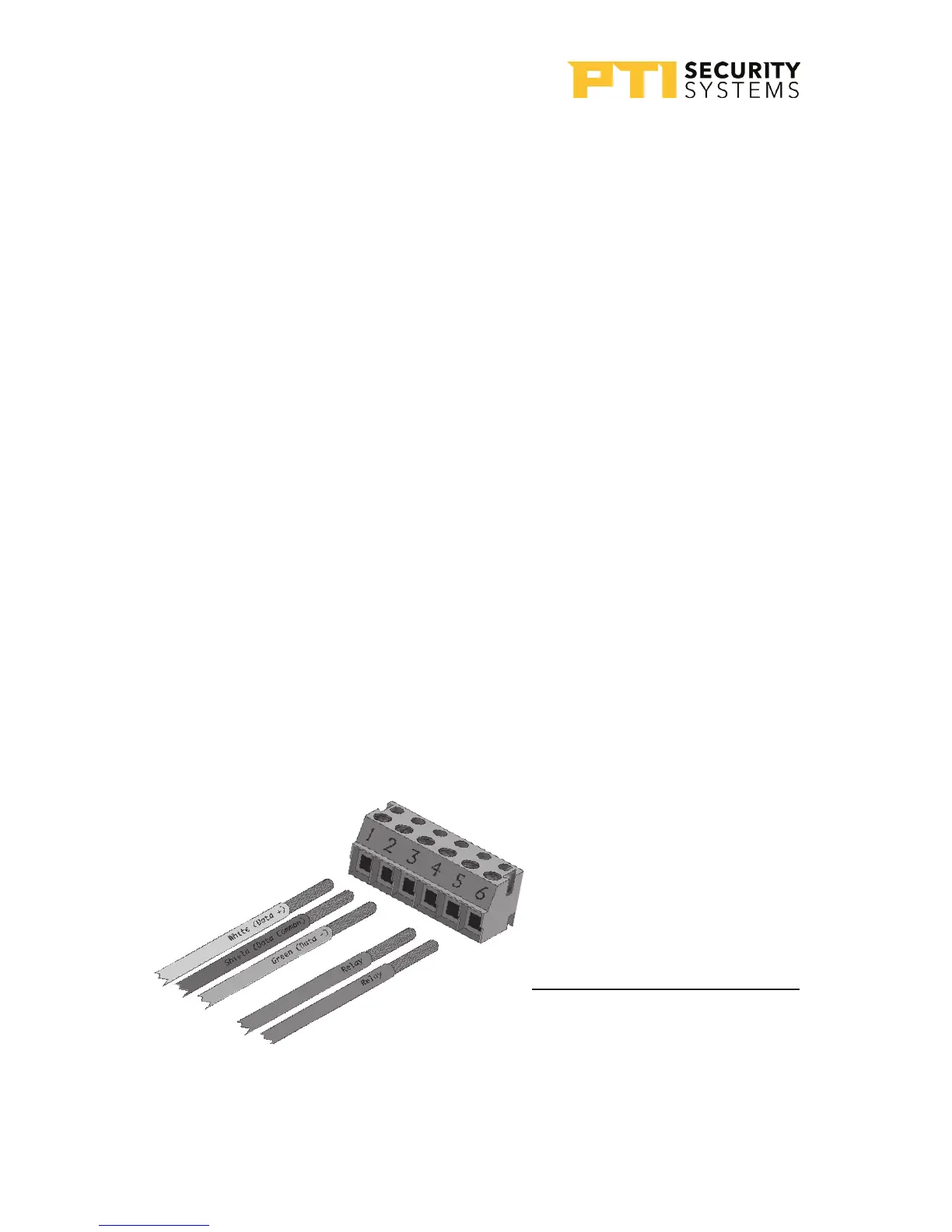
For Terminal block P2 “Drawing 9: Terminal block P2
wiring” on page 12. If a gate operator or door strike is
being triggered directly from this keypad,use pins 4, 5, and
6 for the relay and the wires will connect to two of these three
pins.
Terminal Block P2 (Right)
1. White Data +
2. Shield *
3. Green Data -
4. Relay Normally Open Wire
5. Relay Common Wire
* Shield wire should be
insulated with heat shrink
or electrical tape
Drawing 9: Terminal block P2 wiring