PAGE 26 323 REV.030624
SERVICE INSTRUCTIONS CONTINUED
DANGER
LIFTING A LOAD WITH A NEWLY SERVICED WINCH WILL ENABLE AN
INSTALLATION OR SERVICE PROBLEM TO GO UNDETECTED AND ALLOW
THE LOAD TO DROP CAUSING PROPERTY DAMAGE, SEVERE INJURY
OR DEATH. TO ENSURE PROPER REINSTALLATION, REFER TO PROCEDURES
AND TESTS DESCRIBED IN “INSTALLATION” AND “OPERATING INSTRUCTIONS”.
8) Liberally grease three new O-rings item 801, and install in to recesses on motor adaptor item 800. Install new,
well-greased O-ring item 707, on flange of motor adaptor.
9) Slide hydraulic motor assembly on splined end of motor drive shaft item 730, and line up pressure transfer
holes of brake housing and motor adaptor. Install 12 capscrews item 537, and lockwashers item 541. Tighten
one turn at a time to evenly compress springs.
REASSEMBLY OF HYDRAULIC MOTOR:
If hydraulic motor was disassembled, the following procedure should be followed for reassembly:
1) Clean all parts thoroughly before reassembly and apply grease liberally to all seals. Use only new seals (seal
kit Part No. 23117) for hydraulic motor.
2) Install two new teflon seals item 887, on each thrust plate item 885. Press one of the thrust plates, together
with two teflon seals, onto bearings item 875, installed in motor adaptor item 800.
3)
Install new, well-greased gasket seal item 869, on each side of gear housing item 861. Slide gear housing together
with gasket seals, onto motor adaptor, lined up on two dowel pins. Tap on tight using a soft-headed hammer.
4) Install gear set item 881, in gear housing (the longer gear with the internal spline goes into the top position).
5)
Press other thrust plate, complete with two new teflon seals, onto bearings installed in port end cover.
6)
Install port end cover item 870, together with two bearings item 875, and new ring seal item 877, onto gear
housing, lined up on two dowel pins item 865. Tap on tight using a soft-headed hammer. Install and lightly
torque eight hex capscrews item 951, and lockwashers item 953, to approximately 50 ft-lb (70 Nm).
7) Plumb winch assembly to a hydraulic supply and torque motor capscrews according to the following procedure:
- Ensure that circulation supply flow is being supplied to both the brake housing and the end cover.
- Run the winch, with no load, in the hoisting direction at reduced speed
(approximately 30% of maximum hydraulic volume).
- With winch running, evenly tighten eight capscrews item 951, to 200 ft-lb (270 Nm).
- Test motor operation by running winch at full speed in both directions.
To ensure proper reassembly, run the winch in both directions without load.
6) Slide brake piston into brake housing with hoes for brake springs facing out of brake housing assembly.
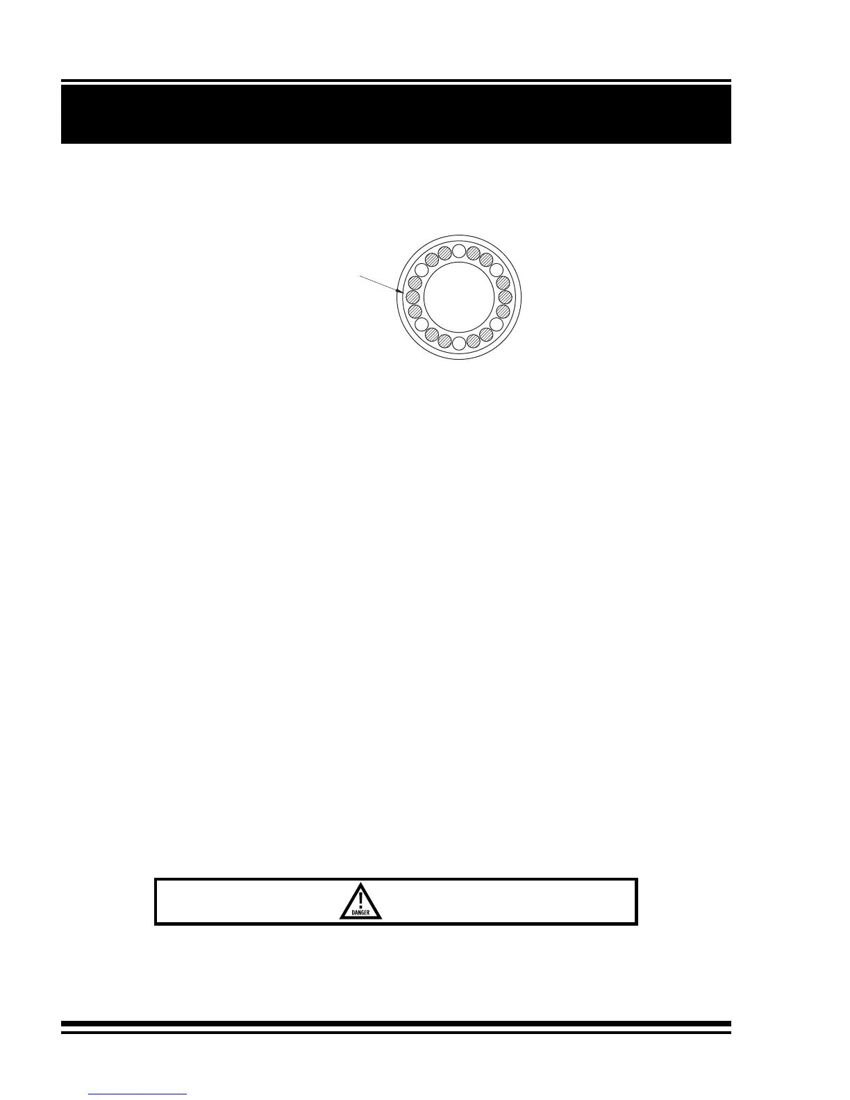
7) Install 14 brake springs item 752, in brake piston using hole pattern shown.
HOLE PATTERN FOR BRAKE SPRING INSTALLATION:
SI1007 - M50
Location of brake springs
(14 springs, 20 holes)