EN
29
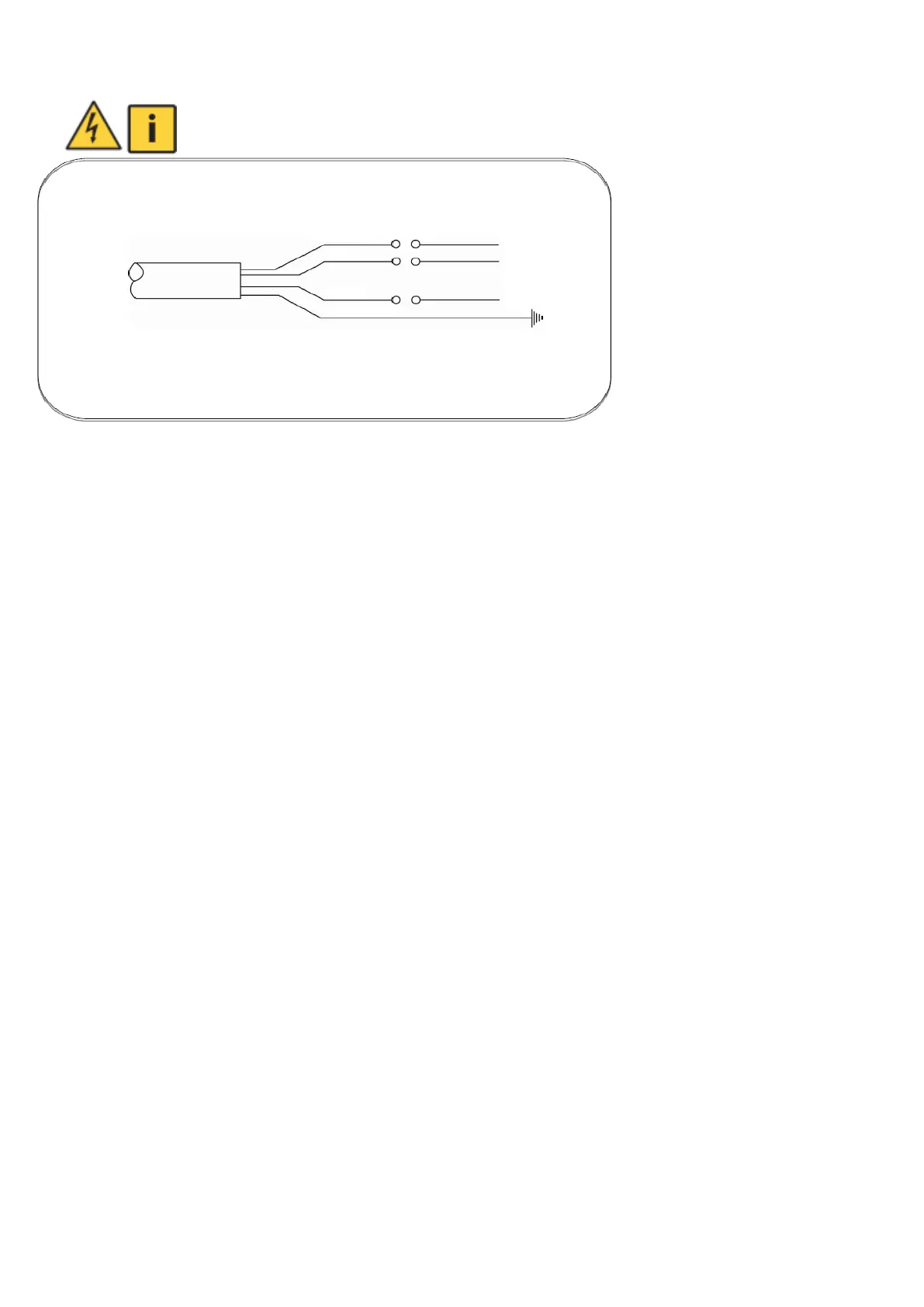
5.6 Wiring diagram
Wiring must not be carried out by a person without electrical qualification.
The colour of the cable (phase) L2 may vary based on Article 13.2.4 IEC 60204
6 Pump installation
6.1 General
Before the actual assembly and installation of the pumping unit, it is necessary to:
1. If the pumping unit is to be installed in a borehole, recheck the entire length of the borehole by lowering a check
cylinder or a 94 mm diameter, 715 mm long pipe. This cylinder or pipe must pass unopposed through the entire
borehole. In this way, the depth of the borehole and, where appropriate, the level in the borehole are determined at
the same time. The minimum borehole diameter for the pumping unit is 100 mm.
2. According to the depth of the borehole or well and the minimum level, the length of the pipe, cable and suspension
line is prepared. The piping must be selected with sufficient strength and with strong joints - taking into account the
weight of the pump set piping and water. It is recommended to use new pipe with well tightened threaded joints. If
plastic piping is used, the pump must only be lowered and raised using a suspension cable. Attach the suspension
line to the pump using the prepared holes in the top of the suction casing.
3. To suspend the unit and the pipe into the excavated well, steel beams are prepared and walled up to safely support
the load. It is recommended that the beams be positioned so that they do not obstruct access to the well. In the case
of drilled wells, the mounting clip may be supported directly on the top edge of the casing, which must be at least as
deep as the pipe leaving the well into the ground. In this case, it is better to extend the borehole to this depth with a
larger diameter, which needs to be cased with large concrete rings as in the case of a drilled well. If plastic pipe is
used, the pump must be lowered and pulled out only by suspension cable.
Between the pump and the safety valve there must be a smooth pipe with a constant cross-section without a shut-off
valve!
In case of use for pressure booster pump, we recommend the installation of a check valve 1“.
6.2 Priming the pump
It is necessary to pour water into the delivery casing. Insert a suitable (flat, square) object into the pump rotor cavity
and turn it about 5 times to the left, then remove the object.
Before inserting the object into the pump rotor cavity, make sure that the pump is disconnected from the mains - risk
of injury from an ejected object if the pump is switched on unexpectedly.
After manual rewinding, proceed to install the pump on the mains to determine the correct sense of rotation of the
pumping unit. It is best to submerge the pump in the vessel as shown.
If the sense of rotation is incorrect, water will not flow out of the pump delivery throat and there is a risk of damage to
the pump.
If the rotation direction is correct (i.e. according to the arrow on the suction unit), water flows out of the delivery
insertion piece.