PuraTech
®
Owner’s Manual 12/11/2013 27
Assembly and Parts, Cont.
Brine Valve Housing Assembly
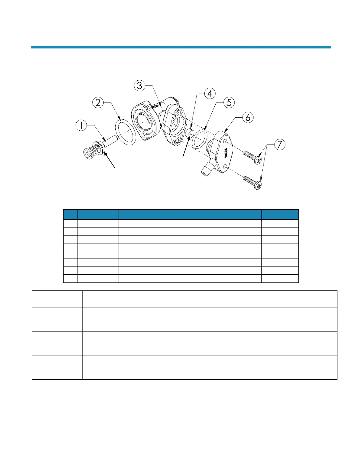
Figure 14: Brine Valve Housing Assembly
Brine Piston Assembly (includes O-Ring & Spring)
Entire Assembly (all of the above parts)
The Piston should have an O-Ring on the shaft side of the flange and a spring pressed onto a boss on
the other side. The O-Ring should be free of defects such as cuts or debris on the shaft side.
Just inside the entrance hole for the Brine Piston is a concave seat area that must be free of defects
such as nicks, indentations, or debris. This seat area ensures a leak-free seal for the static O-Ring on the
Brine Piston. If any defects are detected by visual inspection, repair or replace as needed.
Flow Control
The Flow Button has two distinct and different sides. One is “flat”; the other is “concave.” The button
should be centered in the housing opening with the four locator “ribs” with the concave side facing the
Housing End Cap (Barbed).
End Cap
The Cap is held in place by two 3/4-inch thread-cutting screws that engage the Housing flange. An
O-Ring seals the Cap and Housing. Place the O-Ring onto the housing end cap, lubricate with silicone
grease, and insert the Cap into the housing using a twisting action.
 Loading...