User Manual
PT-E-HD50
Receiving unit PT-E-HD50 RX
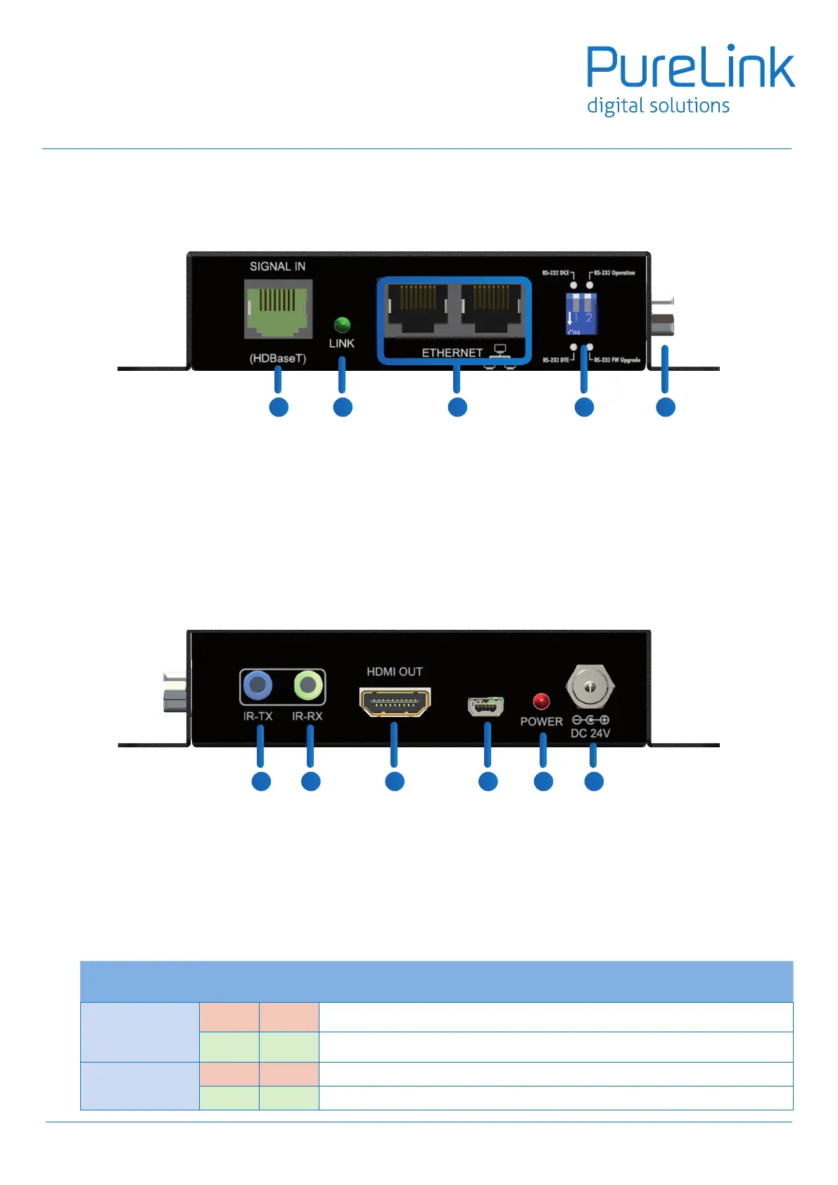
Front Panel
Rear Panel
12. SIGNAL IN: Plug in a Cat-5/5e/6 cable that needs to be linked to the transmitting unit TX.
13. LED: TX /RX link indicator
14. Ethernet port for LAN: Connect to network device
15. DIP Switch:
PIN#1: Setup the RS-232 mode for serial communication channel.
PIN#2: For Firmware Update
16. RS-232: Connect to serial port device with a DSUB-9 male-male or male-female cable here F/W update for
Valens.
17. IR Blaster: Infrared 3.5mm socket for plugging in the extension cable of IR blaster
18. IR Receiver: Infrared 3.5mm socket for plugging in the extension cable of IR receiver
19. HDMI OUT: Connects to a HDMI source with a HDMI male-male cable
20. Mini-USB: F/W update
21. LED: Power indicator
22. +24V DC: Connect to a 24V DC power supply.
7
12
13
14
15
16
17 18 19 20
21 22
DIP Switch Position
TX & RX
Description
PIN#1
ON []
TxD: The 2nd pin of RS-232, which is in charge of sending data
RxD: The 3rd pin of RS-232, which is in charge of receiving data
OFF []
TxD: The 3rd pin of RS-232, which is in charge of sending data
RxD: The 2nd pin of RS-232, which is in charge of receiving dat
PIN#2
ON [] Firmware Update mode
OFF [] Normal
* DIP Switch Position (TX/RX)