- 4 -
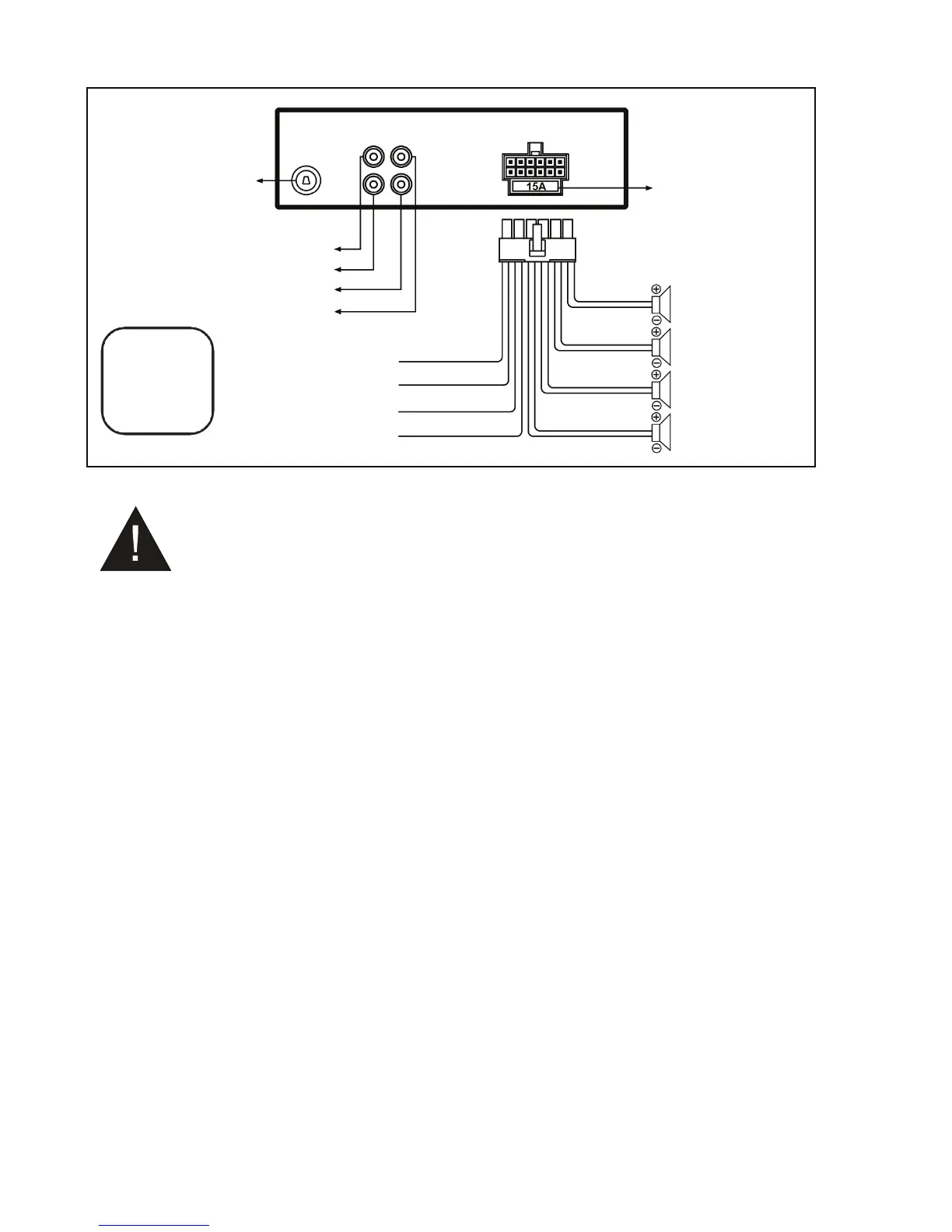
Wiring Connections
WIRING
DIAGRAM
- Only use speakers with 4 ohms impedance.
- The maximum current of the auto antenna is 200mA.
Removal of the Main Unit
1. Remove the plastic trim from the main unit.
2. Insert a bracket key into the left and the right sides of the main unit and draw the unit out of the
mounting sleeve.
Rear Left Speaker
Purple / Black
Radio Antenna Socket
White: Front Left CH RCA Audio Output
Red: Front Right CH RCA Audio Output
White: Rear Left CH RCA Audio Output
Red: Rear Right CH RCA Audio Output
FUSE 15A
GND(Black)
ACC (Red)
Power B+(Yellow)
ANT(Blue)
Rear Right Speaker
Front Right Speaker
Front Left Speaker
Purple
Gray
Gray / Black
White
White / Black
Green
Green / Black
CAUTION
+12V DC
NEGATIVE
GROUND