8
ENFORCER V11 INSTALLATION GUIDE
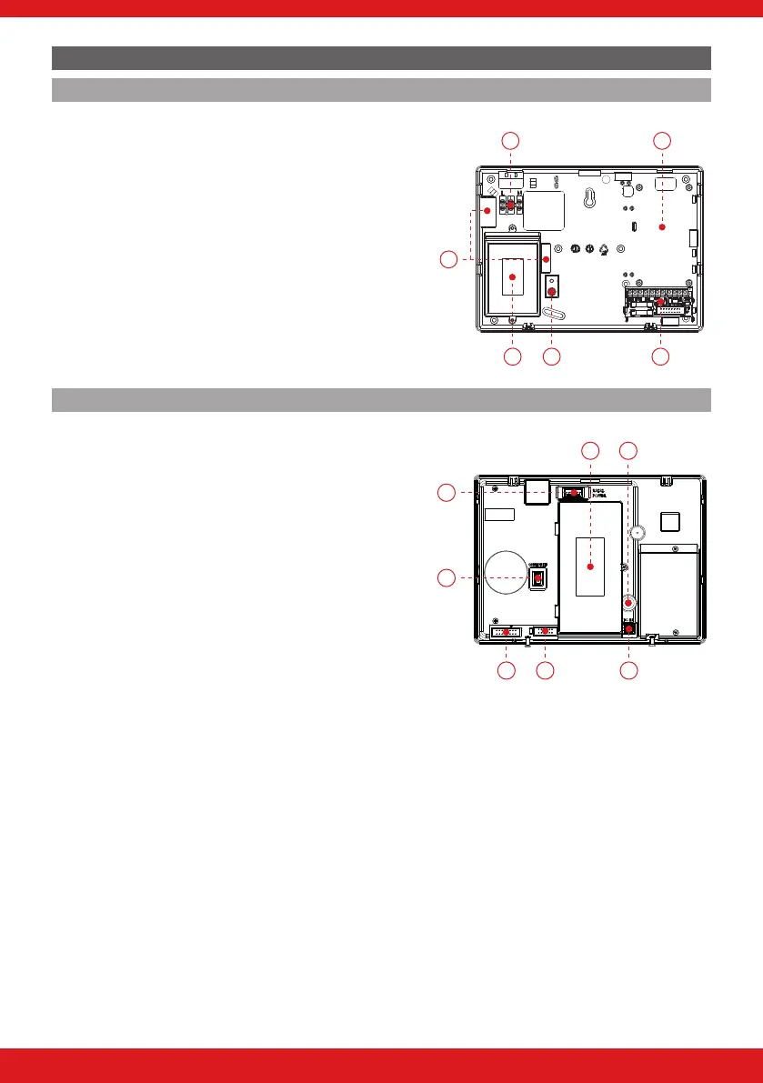
INSIDE OF THE ENFORCER
Back plate
1. Terminals for incoming mains power.
2. If a second communications path is required this space is
used to install the communications module.
DIGI-PSTN, DIGI-PSTN/VOICE, DIGI-GPRS, DIGI-LAN
3. Ferrite beads.
4. The transformer, which is situated in an insulated housing.
5. The rear tamper adjustment screw.
This should be used if the tamper from the front of the Enforcer isn’t sitting ush
to the back plate. E.g. if the Enforcer is installed on an uneven surface.
6. The I/O board.
1
3
2
4 5 6
Front
1. Back up battery compartment.
2. Tamper spring.
3. RS232 connection for upload/download to InSite software.
4. Communications module power connection.
5. I/O board connection.
6. The connection for a communication module to
be installed.
7. Transformer connection. (15VDC)
21
4
5 6 7
3

 Loading...