EasyManua.ls Logo

QEP 60020 - Motor Unit and Frame Assembly; Blade and Guard Installation

QEP 60020
29 pages
Print Icon
To Next Page IconTo Next Page
To Previous Page IconTo Previous Page
Loading...
ENGLISH
ASSEMBLE
MOTOR
UNIT
ON
FRAME
1.
Remove
the
motor
and
motor
mount
assembly
from
the
box.
2.
Insert
the
round
steel
mounting
post
in
the
motor
mount
into
the
hole
in
the
upright
support,
as
shown
in
the
illustration
to
the
right.
Make
sure
the
round
mounting
post
is
fully
inserted
in
the
hole
of
the
upright
support.
3.
Secure
the
round
steel
post
with
the
hex
head
bolt
(2%"
long,
3/8"
diameter)
and
washers
supplied.
4,
Secure
the
motor
unit
to
the
vertical
adjustment
bracket,
using
the
bolt
|
and
washer
with
the
largest
plastic
knob
in
the
parts
kit.
(Part
1031).
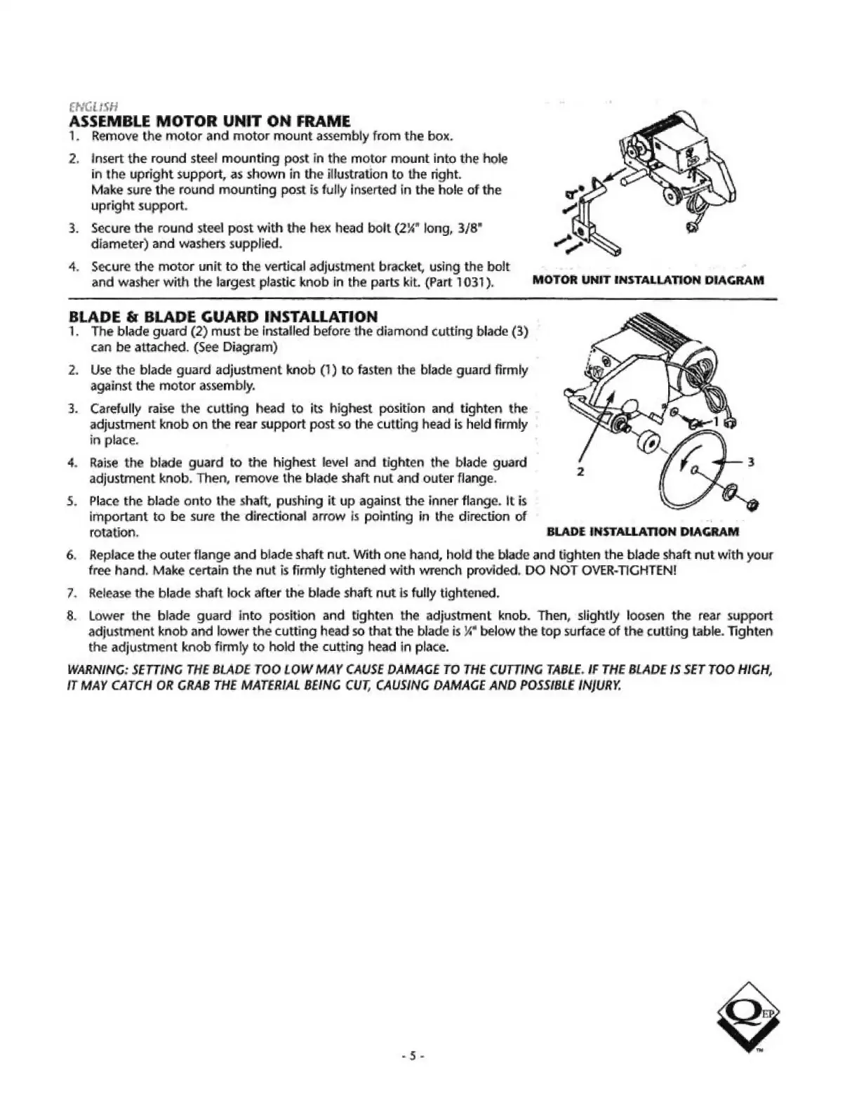
MOTOR
UNIT
INSTALLATION
DIAGRAM
MEADE
&
BLADE
GUARD
INST.
ALLATION
The
blade
quard
(2)
must
be
installed
before
the
diamond
cutting
blade
(3)
can
be
attached.
(See
Diagram)
2.
Use
the
blade
guard
adjustment
knob
(1)
to
fasten
the
blade
guard
firmly
against
the
motor
assembly.
3.
Carefully
raise
the
cutting
head
to
its
highest
position
and
tighten
the
adjustment
knob
on
the
rear
support
post
so
the
cutting
head
is
held
firmly
in
place.
4.
Raise
the
blade
guard
to
the
highest
level
and
tighten
the
blade
guard
adjustment
knob.
Then,
remove
the
blade
shaft
nut
and
outer
flange.
5.
Place
the
blade
onto
the
shaft,
pushing
it
up
against
the
inner
flange.
It is
important
to
be
sure
the
directional
arrow
is
pointing
in
the
direction
of
rotation.
BLADE
INSTALLATION
DIAGRAM
6.
Replace
the
outer
flange
and
blade
shaft
nut.
With
one
hand,
hold
the
blade
and
tighten
the
blade
shaft
nut
with
your
free
hand.
Make
certain
the nut
is
firmly
tightened
with
wrench
provided.
DO
NOT
OVER-TIGHTEN!
Release
the
blade
shaft
lock
after
the
blade
shaft
nut
is
fully
tightened.
8.
Lower
the
blade
guard
into
position
and
tighten
the
adjustment
knob.
Then,
slightly
loosen
the
rear
support
adjustment
knob
and
lower
the
cutting
head
so
that
the
blade
is
4"
below
the
top
surface
of
the
cutting
table.
Tighten
the
adjustment
knob
firmly
to
hold
the
cutting
head
in
place.
WARNING:
SETTING
THE
BLADE
TOO
LOW
MAY
CAUSE
DAMAGE
TO
THE
CUTTING
TABLE.
IF
THE
BLADE
15
SET
TOO
HIGH,
IT
MAY
CATCH
OR
GRAB
THE
MATERIAL
BEING
CUT,
CAUSING
DAMAGE
AND
POSSIBLE
INJURY.

Table of Contents