Version: 13. September 2004
15
[ ]IC7 AT90S2313 (programmed) A/B7
The following part is an integrated 25 MHz oscillator. Pin 1 is marked on
the part and in the placement diagram.
[ ]IC8 25MHz oscillator C7
Take care of statics, the next transistor is very sensitice against
Electro Static Discharge (ESD)
[ ]T2 BF199 C6
[X] IC6 AD9835 TSSOP16 B6/7 SMD
[ ]R9 1,5K B6
[ ]R10 100K C6
[ ]R12 270R C7
[X] R13 3,9K SMD 0805 C7
[ ]R14 680R B7
[ ]R15 not used B7
[ ]R16 10K A7
Now follows two SMCC RFCs. They look like fat resistors. Measu-
ring them with an ohmmeteres, they are close to 0 Ohm. The
colour coding is as with resistors, but due to their light bodies,
they are easier to read.
[ ]L2 4,7µH SMCC C6
[ ]L3 4,7µH SMCC C7
Now we mount a crystal in HC18 casing. Mounting crystals, it is necessary
to avoid shorts on the pc board from the casing. To avoid this, the crystal
is mounted at a short distance from the pc board, or by putting an isola-
ting disc below the crystal. A common way to do it is to place to cut off
leads from resistors temporarily under the crystal as placeholders, during
soldering. Remember to remove the resistor leads again after soldering!
[ ]Q1 4,096MHz HC18 B6/7
[ ]St3 connector A6
[ ]St4 connector A/B7
[ ]PIN7 A/B7
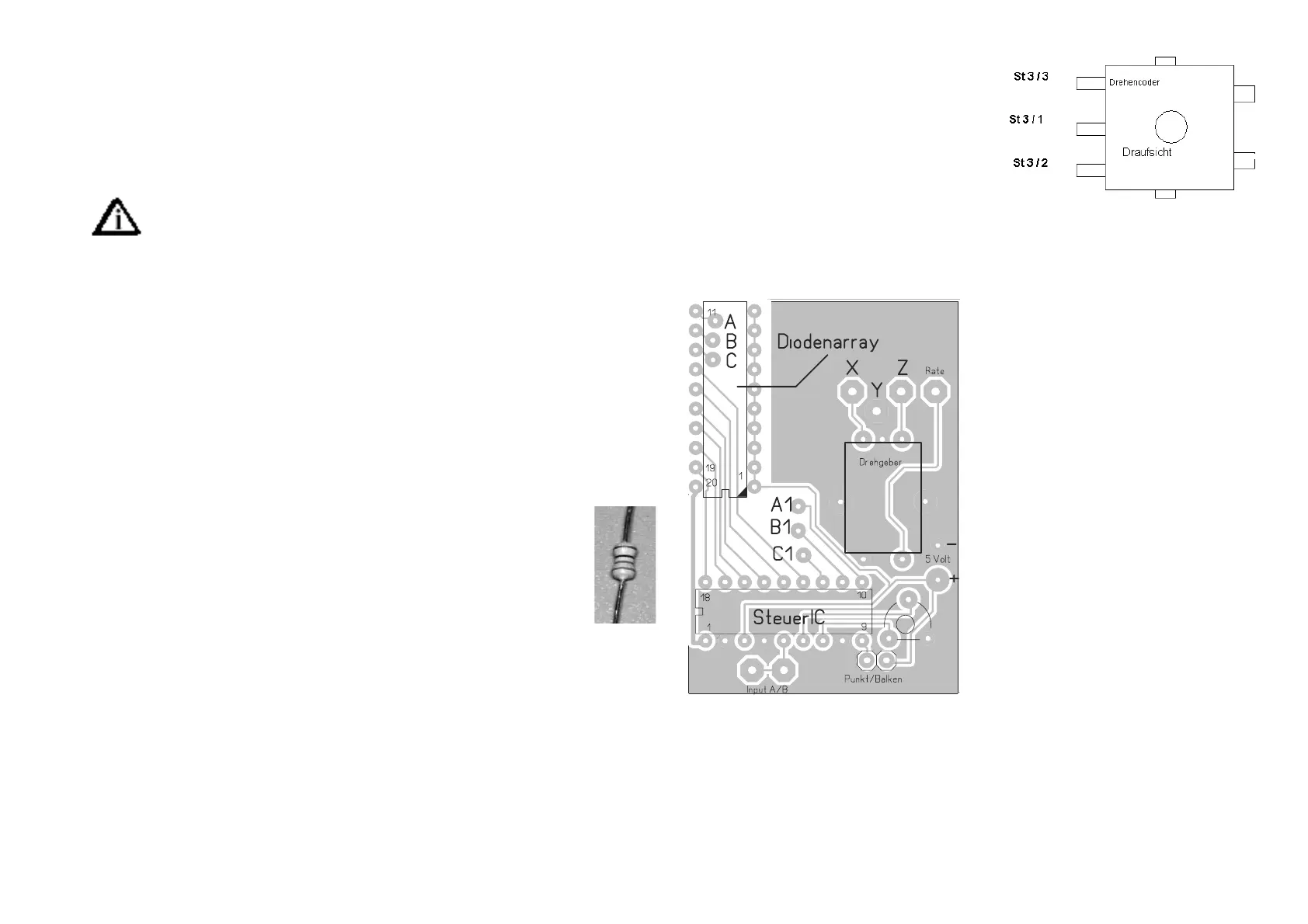
To use the section, the rotary encoder
should be connected. If you got the kit
including the Bargraph.S-Meter, go to
step “Building the S-Meter now. The 3-Pin Plug, ready with 3 wires is do
make the connection to ST3 on the main board. Twist the 3 wires and solder
them directly to the encoder solderlugs as you can see in the drawing right.
Assembling the S-Meter / Power-
meter / Encoder- PCB
This is a single sided PCB. You need 3
wire bridges to make functional. Solder
the 3 wires first. Solder them at the
parts placement side of the PCB. Us
thin wire to make it possible to place
the bargraph flat in the next step.
[ ] Wire from A to A1
[ ] Wire from B to B1
[ ] Wire from C to C1
Next place the bargraph, DO NOT USE a
Socket. Be carefull to identify PIN 1,
compare the chip to the drawing.
[ ] Solder the bargraph
[ ] Solder the Encoder
[ ] Solder the control IC (Steuer IC), attention PIN 1!
Attention, the next parts have to be placed and soldered to the solder Side
of the PCB
[ ] Trimpot
[ ] 2 Pin Jack for jumper
[ ] Solder PINs