Version: 13. Sepe,mer 2004
18
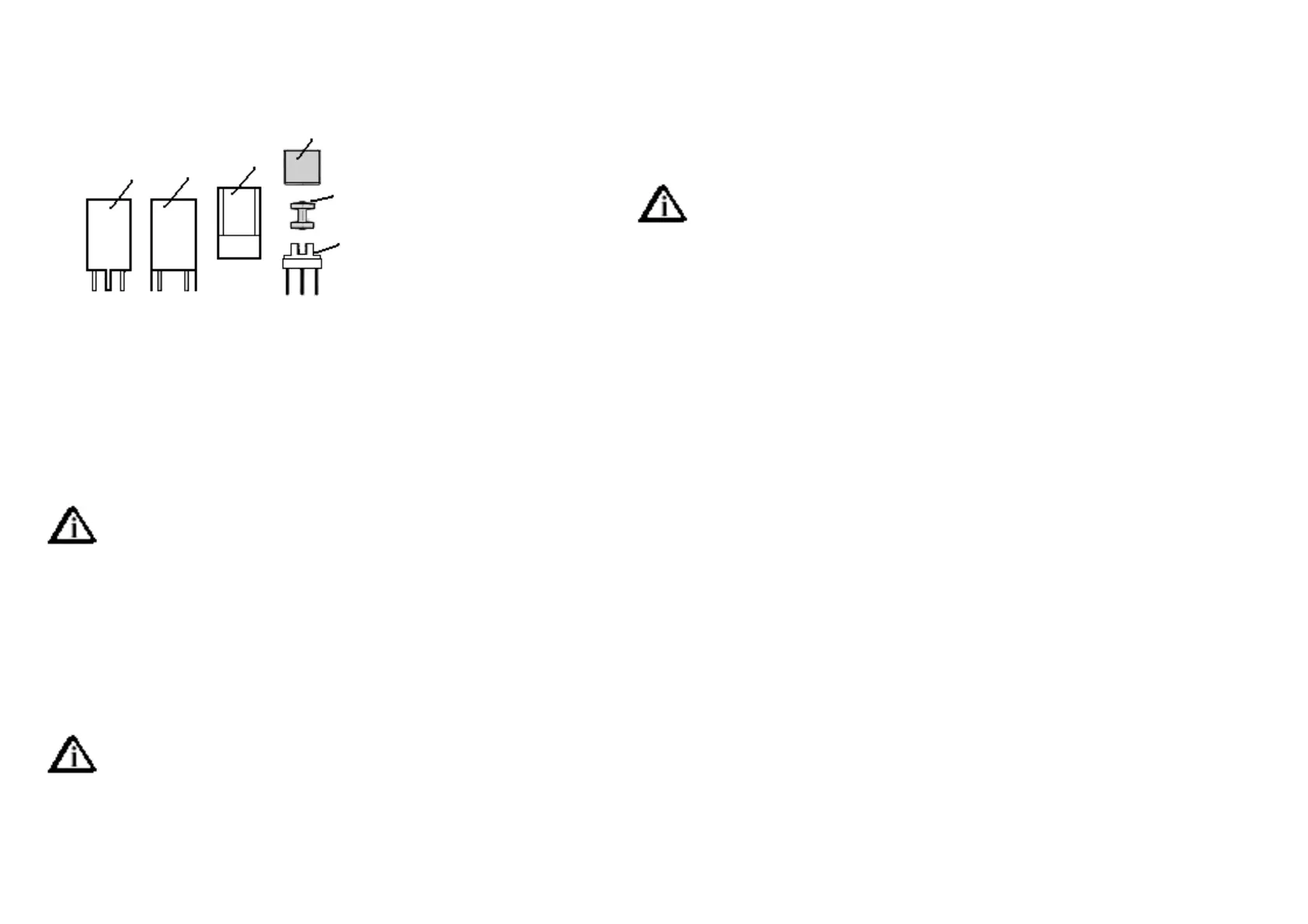
Building Group 5, Carrier Oscillator and Switches
The Neosid coil, used in this group is completely different from the known
Neosid cylinder coils. Here we are
using a so called BOBIN coil. The
kernel is made from ferrite mate-
rial, which is looking like a reel.
The windings on this kernel are
not brought on, turn for turn, but
simply winded as are. The only
importance is the right number of
windings.
1=Shield Can 2= Guidance from Plastic 3 Kernel
4= Coilbody 5= Socket
Take the socket of the Bobin and put a little drop of Super glue between
the kernelholders and press carefully the Ferrit bobbin into the holders.
Wait until the glue is dry before continuing the work. You are free to solder
other parts in the meantime.
Caution! IC12 is sensitive against static charging. Discharge
yourself before rolling the part.
[ ] IC12 4066 DIL14 D2
PT6 we already knows. These are the little black trim-potentiometers
[ ]P71K PT6 lying B2
Spectrol 75H are precision-trim-potentiometers in a metal case.
Caution, first compare the three terminals exactly with the
respective holes on the pc board. The trim-potentiometers are
gliding very easy into the holes, if they are mounted right. If
you need pressure, they are mounted the wrong way!
[ ] P8 10K Spectrol 75H D2
[ ] P9 10K Spectrol 75H D1
[ ] P11 10K Spectrol 75H D2
[ ] P10 10K Spectrol 75H D1
[ ] D29 BB109G / BB409 or equivalent C1
[ ] D30 BB109G / BB409 or equivalent C1
The following transistors are mounted according to the place-
ment diagram. Caution! they are sensitive against static char-
ging. Discharge yourself before rolling the part.
[ ] T20 BF199 B2
[ ] T21 BS250 MOS beware of static! E2
[ ] T22 BS250 MOS beware of static! E2
The crystal is mounted with the help of two cut off resistor leads.
[ ] Q6 8,000MHz HC18 B1
[ ] Q7 8,000MHz HC18 B1
[ ] R89 47K B2
[ ] R90 47K B2
[ ] R91 68k C1
[ ] R92 39K C/D2
[ ] R93 39K D2
[ ] R94 39K D/E2
[ ] R95 100K D1/2
[ ] C97 1nF 102 B3
[ ] C119 22nF 223 A/B2
[ ] C120 330pF 331 or n33 B2
[ ] C121 220pF 221 or n22 B2
[ ] C122 10nF 103 C1/2
[ ] C123 100nF 104 C2
Now the coil form should be glued properly, and the coil can be wound.
The picture shows the coil from below. Start at pin „anfang“, by twisting
the 0.1 mm wire three times around the pin, and then through the notch