Version: 13. Sepe,mer 2004
40
Now the adjustments of the SSB stage are finished.
Adjustments of the Band Modules
The different band modules will be now adjusted, as described for the 40 m
band module. For each module the LO has to be adjusted first. Therefore
the VCO has to be adjusted in a way, that at the starting frequency of the
DDS the VCO trimmer is set to get 1.5 Volts at the loop filter. With the
trimming potentiometer a RF-Level of 100 mV rms at the bus line is adjus-
ted. At the jumper for the ring mixer it should be 7 dBm (jumper at 50 Ohm
position) which equals 1.4 Volts peak to peak.
The bandpass filters of each module will be adjusted as follows: Adjust to
the middle of each band and set the preselektor trimmer to its middle
position. While in mode CW and Tx key pressed, adjust both of the band
pass trimmers until a definite and single transmitting power maximum
occurs. Tuning should be done at as low transmitting power as possible.
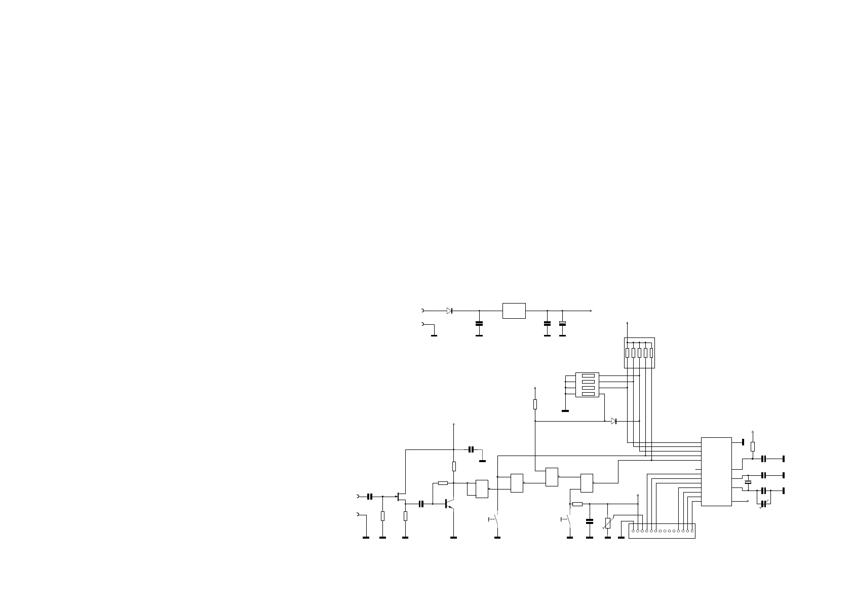
Building the Frequency Counter
Introduction
Frequency counters using PIC are already known a long time in different
forms. Thereby the basic features like frequency range, resolving and sensi-
tivity are always identical. We were looking for a multiple usable counter
which could be used as a single device, but also as a module for a multi-
functional set. Finally we found a module which came near to our imagina-
tions.
The counter was developed by Ron Taylor, G4GXO, based on publications of
other OM’s. These therefore founded the basics of the present product. Ron
describes the circuit in the internet (http://www.g4gxo.cwc.net/) from
where also may be downloaded the software.
We thank Ron Taylor, G4GXO, who developed the counter for us in the
present form, Dr. Peter Halicky, who contributed essential basics and ideas
for the Software, Ed Skelton, EI8GQ, who contributed ideas for the hardware
&
&
&
&
J1
J2
C1
10n
C2
10n
C3
100n
C5
33p
C6
22p
C7
100n
C8
100n
C9
100n
C10
47µ
R1
2M2
R2
220
R3
10k
R4
470
R5
1k
R6
33k
R7
10k
T1
J310
T2
BF199
S1 S2
C4
100n
RA0
RA1
RA2
RA3
T0 CKI/RA4
RB0
RB0RB1
RB2
RB3
RB4
RB5
RB6
RB7
VSS
MC LR\
OSC2
OSC1
VD D
17
18
1
2
3
6
7
8
9
10
11
12
13 14
16
15
4
5
IC2
16F 84
1 2 3 4 5 6 7 8 9 10 11 12 13 14
J3
LCD 2x16
C11
25p
D1
1N4148
1234
5678
ON
1234
DIP1
2345
1
6
Array1
5x4k 7
+5V
+5V
+5V
+5V
+5V
+5V
IN O UT
GND
IC3
78L05
D2
1N4004
+5V
Xtal1
4MHz
4
5
6
8
10
9
11
12
133
1
2
IC1/1
IC1/2
IC1 / 3
IC1 /4
P1
10k
Zähler DL-QRP-AG Vers. 18. 12.02 Zchng Jürgen, DL1JGS