Version: 13. Sepe,mer 2004
4
switchable HF bands. Based on the Black Forest, the Tramp and the Spar-
row, it was possible to develop a kit in 4 months, primarily using conventi-
nal parts (only some 12 SMD’s), for a 5 band SSB/CW transciever, leaving
nothing to want for its price class. Peter, DL2FI, nicknamed it SPEAKY (
Gonzales) as complement to the Miss Mosquita. The following data speaks
for themselves:
Speaky technical data:
- From 1 to 5 HF bands switchable from the front of the box.
- Modulation: SSB/ CW/ PSK31 etc.
- Power input: 10W PEP
- DDS/ PLL- frequency control, with programmable frequency
steps.(rotary encoder)
- choice of RIT or XIT; integrated keyer
- VFO tuning range 500KHz
- optional digital frequency readout.
- automatic bandwith selection ( 2,4KHz/ 600Hz) of the 4pole 8MHz-
crystal filter
- tunable high Q preselector
- High current RF input circuit with dynamic feed back.
- +7dBm- Schottky- ring mixer ( TUF- 1)
- High current J- FET IF amplifier
- > 90dB IF dynamic range (A244 IC)
- AGC production with peak to peak rectifier.
- AF section with power for loudspeaker
- robust PA with 2 x 2SC1969
- Transmitter output of 10W PEP
- switchable harmonics filter
- integrated speech compressor with a compression of max. 15: 1
- [please change this] Modulationsklirrfaktor of the compressor < 1% !!
- adjustable transmitter power
- CW- VOX with adjustable decay
- 10,8- 15V power supply
- Stable enclosure with prepunche holes
- Digital Frequency readout - measuring LO frequency
- Bargraph S-meter/relative Power Meter
Description of the individual stages:
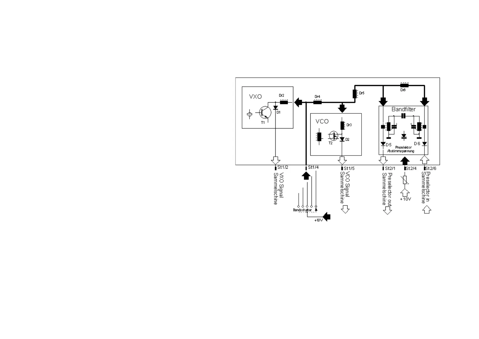
1. Band switching:
One of the main qualities of the transceiver is the ability to switch up to 5
HF band modules. To conserve space, only electronic switching was conside-
red. All band specific parts are mounted in replaceable band modules. The
following sections are switched when changing bands.:
- VCO
- Band set oscillator
- RX/ TX preselector
The inputs and outputs of all band modules are connected via the PIN
diodes D1- D2- D5- D6 to a common bus. The 10V switching signal activates
the diodes of the corresponding HF module. The chosen module is RF-wise
connected to the bus. All other diodes on the inactive modules are blocked
and high impedance. The systems impedance of the RF ports is some 50-
100 Ohms, so the inactive modules are effectively decoupled.